Device for screwing caps onto containers

Inactive Publication Date: 2007-03-29
KRONES AG
View PDF5 Cites 15 Cited by
  • Summary
  • Abstract
  • Description
  • Claims
  • Application Information

AI Technical Summary

Benefits of technology

[0004] The task which forms the basis for the disclosure lies in creating a device for screwing caps onto containers in which it is possible t

Problems solved by technology

A change of the closing- or opening position of the gripping tongs, as the case may be, requires a time-consuming replacement of the control curve.
In addition, the manufacturing and assembl

Method used


Image

  • Device for screwing caps onto containers
  • Device for screwing caps onto containers
  • Device for screwing caps onto containers

Examples


Embodiment Construction

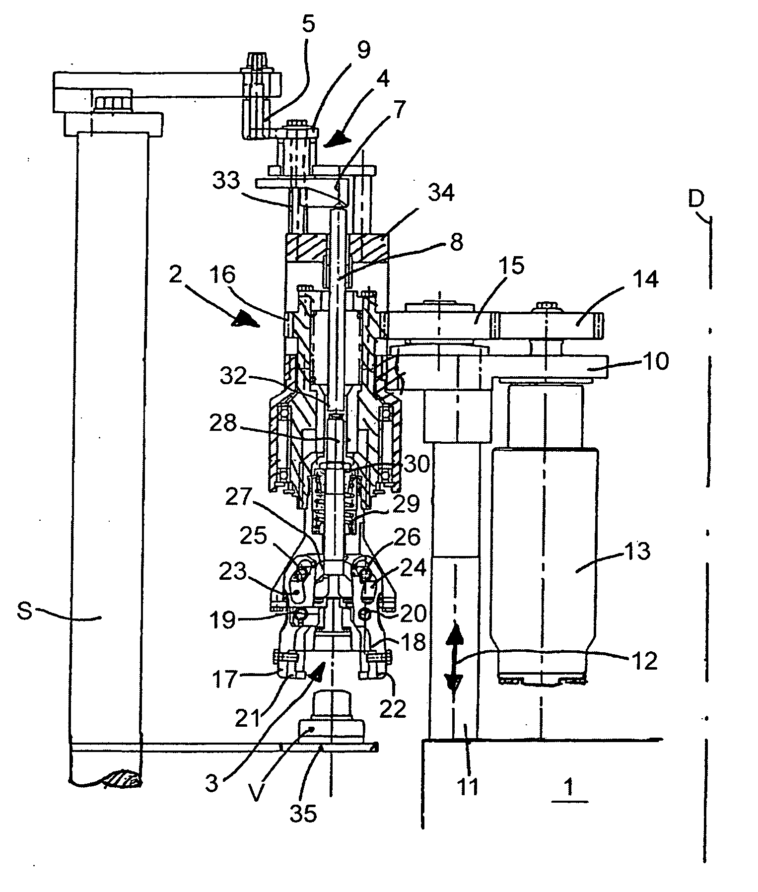
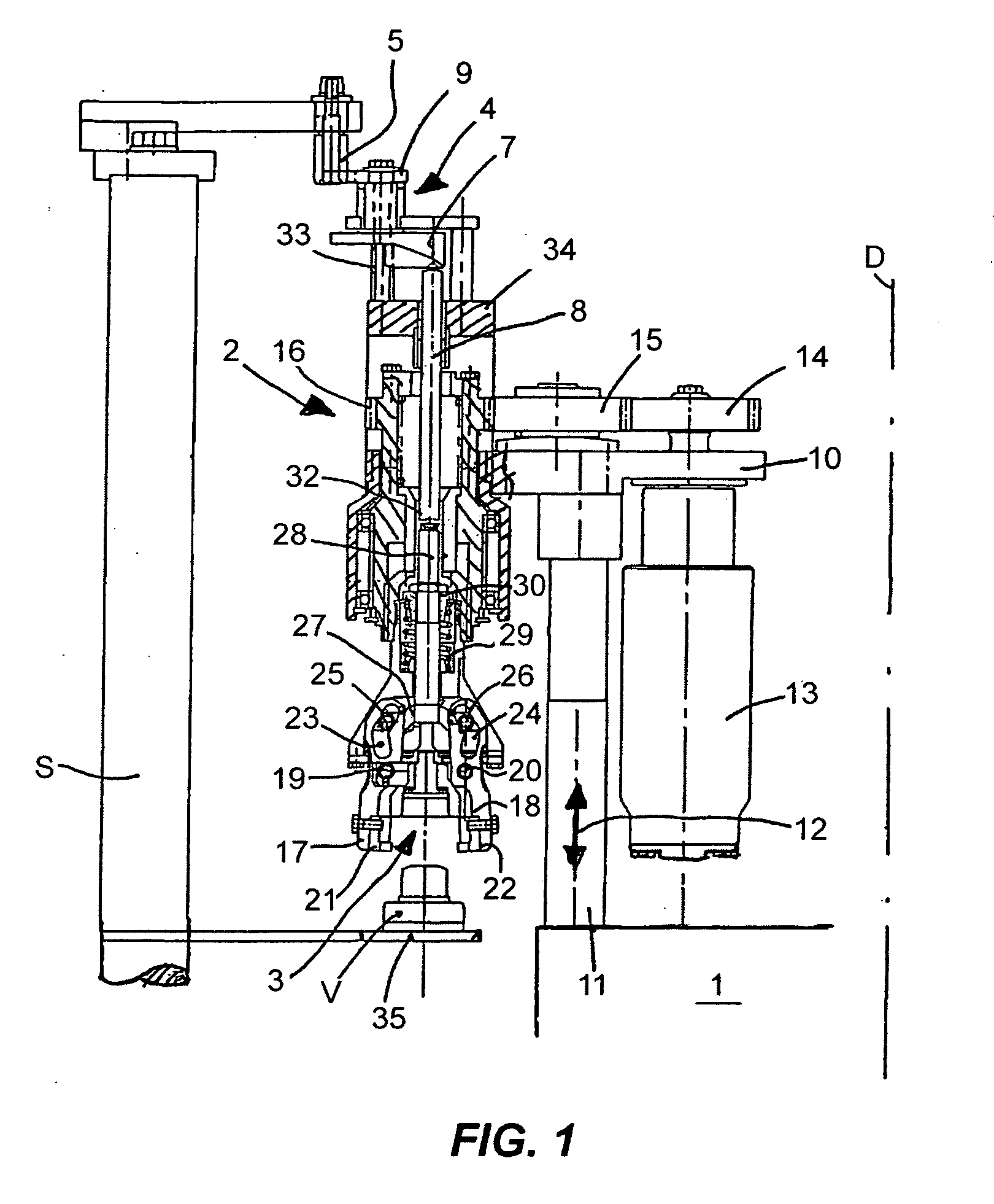
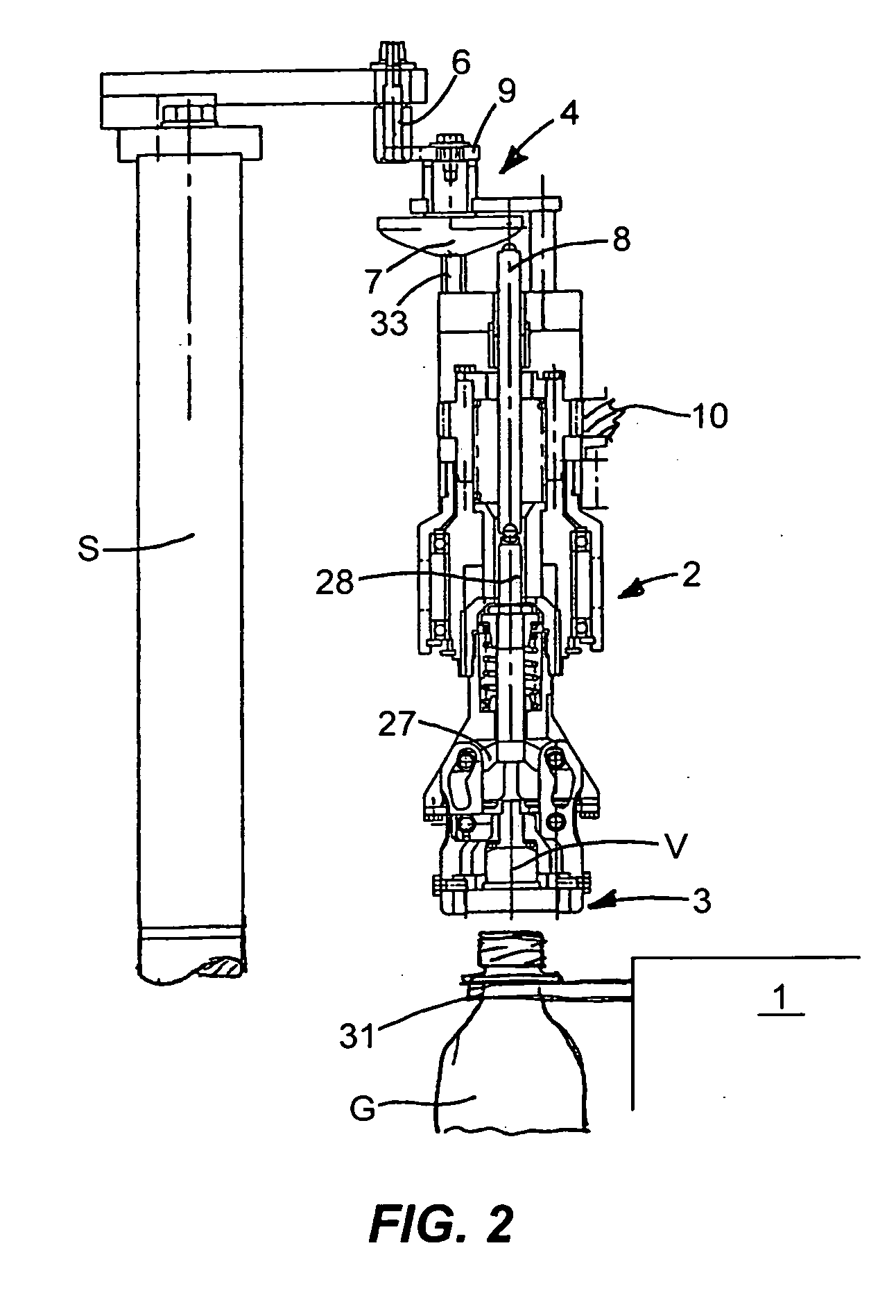
[0016] The device in accordance with the FIGS. 1, 2 and 5 is designed for the screwing of sealing caps (V) of plastic, which are provided with an internal threading, onto containers (G), in the form of PET bottles for beverages. It has a rotor (1) revolving around a vertical rotational axis (D), on which rotor several closing heads (2) are positioned distributed uniformly over the circumference, which heads revolve on a circular track (K).

[0017] Every closing head (2) is supported in a rotatable manner in a horizontal bearing bracket (10), which bearing bracket is, for its part, attached to a vertical column (11). This is accommodated in the rotor (1) in a controlled, height-adjustable manner by means of a lifting curve, not depicted, as indicated by the double arrow (12). An electrical servomotor (13) is additionally attached to the bearing bracket (10); this servomotor sets the closing head (2) into rotation by means of toothed wheels (14, 15, 16) at predetermined areas of its ci...


PUM


Abstract

A device for screwing caps onto containers with several closing heads revolving on a closed track, each closing head having a controllable gripping tong, a control unit for the opening position and the closed position of the corresponding gripping tong, with each control unit revolving along with and allocated to every gripping tong. The revolving control units can be reversed in direction between the opening position and the closed position by stationary stops. In this manner, a precise and rapid reversal of the gripping tongs, as well as a simple adjustment of the opening- and closed position, is made possible without a stationary control curve.

Description

CROSS-REFERENCE TO RELATED APPLICATION [0001] This is the U.S. national stage under 35 U.S.C. §371, of international application no. PCT / EP2004 / 013599, having an international filing date of Dec. 1, 2004, and claims priority to German application no. 103 56 222.2 filed on Dec. 2, 2003.FIELD OF THE DISCLOSURE [0002] The disclosure relates to a device for screwing caps onto containers, such as used in bottling operations. BACKGROUND OF THE DISCLOSURE [0003] Such a device is already known, in which the activation of the gripping tongs for the closures is carried out by means of a stationary control curve in which curve rollers revolving on a circular track engage with the gripping tongs (SU-PS 1 736 915). Because of the maximum permissible gradient of the curve, the time for the closing- and opening movement of the gripping tongs is thereby relatively great, which stands in the way of high capacities. A change of the closing- or opening position of the gripping tongs, as the case may b...

Claims


Application Information

Patent Timeline
IPC IPC(8): B65B7/28B67B1/06B67B3/20
CPCB67B3/2033
Inventor LANG, HORSTWREDE, MARTINA
Owner KRONES AG
Why Eureka
Try Eureka