Circuit and method for contact-less transmission

a contact-less transmission and circuit technology, applied in the field of contact-less connection, can solve the problems of poor quality of the signal received at the first module, and achieve the effect of improving the contact-less transmission of signals

Inactive Publication Date: 2007-03-29
TYCO ELECTRONICS BELGIUM EC
View PDF11 Cites 13 Cited by
  • Summary
  • Abstract
  • Description
  • Claims
  • Application Information

AI Technical Summary

Benefits of technology

[0005] The object of the present invention is to provide a circuit and method allowin

Problems solved by technology

In the systems according to the prior art, however, the qual

Method used


Image

  • Circuit and method for contact-less transmission
  • Circuit and method for contact-less transmission
  • Circuit and method for contact-less transmission

Examples


first embodiment

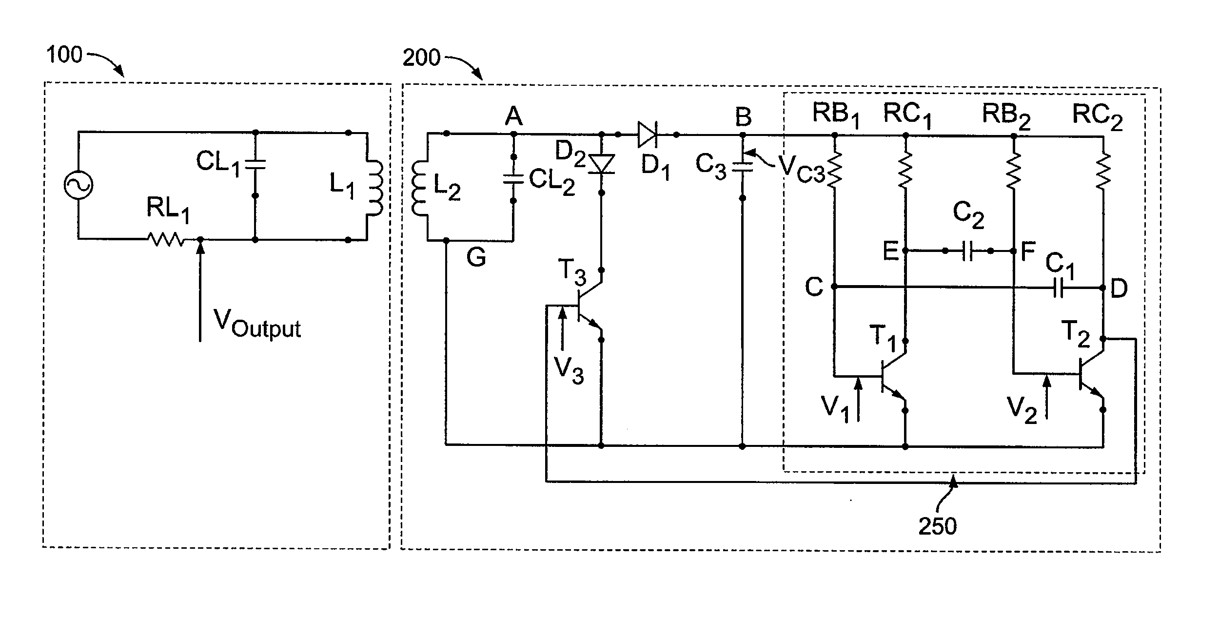
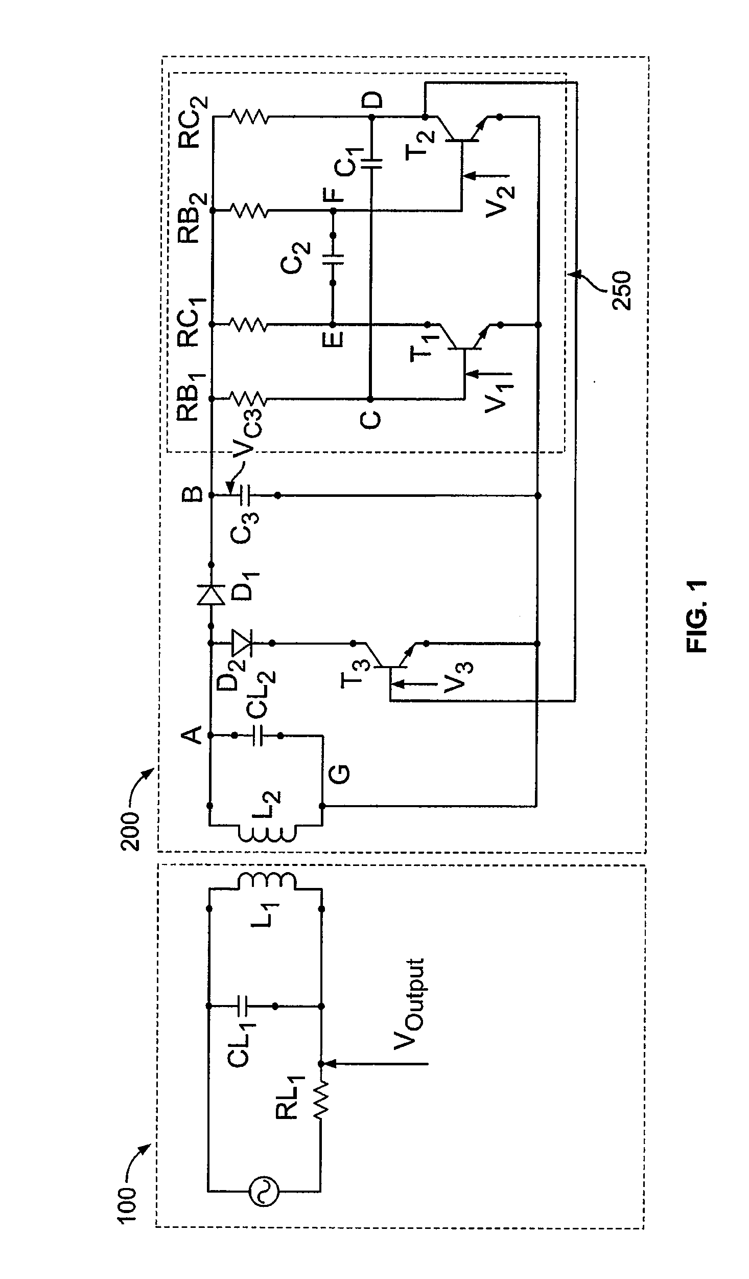
[0022]FIG. 1 shows a system consisting of a first circuit 100 and a second circuit 200 for establishing a contact-less transmission according to the present invention. The first circuit 100 (further circuit) comprises a first inductor L1 while the second circuit 200 (circuit) comprises a second inductor L2, so that the first circuit 100 and the second circuit 200 form, respectively, a primary and secondary circuit of a transformer. The first and second inductors L1, L2 therefore interact by a magnetic coupling.

[0023] The first circuit 100 is connectable to a signal generator, such as an alternating signal generator. The signal generator generates a signal which is transmitted inductively from the first inductor L1 of the first circuit 100 to the second inductor L2 of the second circuit 200. The second inductor L2 of the second circuit 200 is part of a resonant circuit, which includes a capacitor CL2 connected in parallel with the second inductor L2. The signal transmitted inductivel...

second embodiment

[0040]FIG. 4 shows a system consisting of a first circuit 100 and a second circuit 200′ according to the present invention. Since the first circuit 100 is substantially identical to the first circuit 100 described with respect to FIG. 1, further description of elements thereof will be omitted hereafter.

[0041] The second circuit 200′ comprises an inductor L2 which forms a resonant circuit with a capacitor CL2. A rectifying element, such as a diode D1, is arranged in such a way that the diode D1 rectifies an excitation signal output by the resonant circuit. An anode of the diode D1 is connected to a connection point A, which is located between the inductor L2 and the capacitor CL2. A cathode of the diode D1 is connected to a resistor R1. A capacitor C1 is connected in series with the resistor R1 and to a connecting point H, which is located between the inductor L2 and the capacitor CL2. The connecting point H is different from the connecting point A. A resistor R2 is connected in para...


PUM


Abstract

A system includes a first and second circuit electromagnetically coupled to establish a contact-less transmission, for example, between a vehicle body and a removable seat of the vehicle body. The first circuit includes a first inductor and the second circuit includes a second inductor. In order to detect in the first circuit the status of one or more input signals of the second circuit, the second circuit includes a signal generating portion including a resistor and a capacitor that generates, a time-pulsed signal. The second circuit is adapted to set a value of at least one of the resistor and the capacitor based on a sensed parameter and sets a duty cycle of the time-pulsed signal based on a value of at least one of the resistor and the capacitor. The time-pulsed signal changes a load of the second circuit over time which can be detected in the first circuit.

Description

FIELD OF THE INVENTION [0001] The present invention relates to a contact-less connection between electrical modules, and in particular a system having a first circuit and a second circuit electromagnetically coupled to establish a contact-less transmission, for example, between a vehicle body and a removable seat of the vehicle body or between a dashboard and a steering wheel, as a wireless clockspring. BACKGROUND OF THE INVENTION [0002] In many vehicles manufactured nowadays, removable seats are foreseen that comprise an electrical module adapted to communicate in a contact-less manner with another electrical module fixed on a vehicle body. A possible solution is to arrange a first module comprising a first inductor on the vehicle body and a second module comprising a second inductor on a removable seat. The first module and the second module are arranged on the vehicle body and on the removable seat, respectively, in such a way that a spacing between the first and second inductors...

Claims


Application Information

Patent Timeline
IPC IPC(8): H04Q7/00
CPCB60R16/027
Inventor OCKET, TOMFRYNS, JOERICAUWENBERGE, JAN VANSIOTTO, MICHAEL
Owner TYCO ELECTRONICS BELGIUM EC
Why Eureka
Try Eureka