
Bulk transfer dispensing device and method

a technology of dispensing device and liquid transfer, which is applied in the direction of liquid transferring device, pliable tubular container, transportation items, etc., can solve the problems of affecting the operation of the pump, affecting the efficiency of the pump, and affecting the efficiency of the devi

Active Publication Date: 2007-04-12
PORTEC RAIL PRODS
View PDF33 Cites 6 Cited by
  • Summary
  • Abstract
  • Description
  • Claims
  • Application Information

AI Technical Summary

Problems solved by technology

However, the apparatuses utilizing pumps often are interrupted in the emptying process to prevent air pockets from being created while emptying the container.
Further, by pumping out the fluid, waste is problematic in that residual material remains on the walls of the container.
These devices are typically limited to materials having lower viscosity levels, thus only requiring minimal levels of force to encourage the dispensing of the fluid.
These systems are expensive because of the internal control systems required to allow the rollers and pump to operate in a proper sequence.
Further, these systems are not equipped to be easily maneuvered for operating in environments where strict spatial dimensions may be imposed in which the dispensing apparatus may be required to operate within.

Method used


Image

  • Bulk transfer dispensing device and method
  • Bulk transfer dispensing device and method
  • Bulk transfer dispensing device and method

Examples


first embodiment

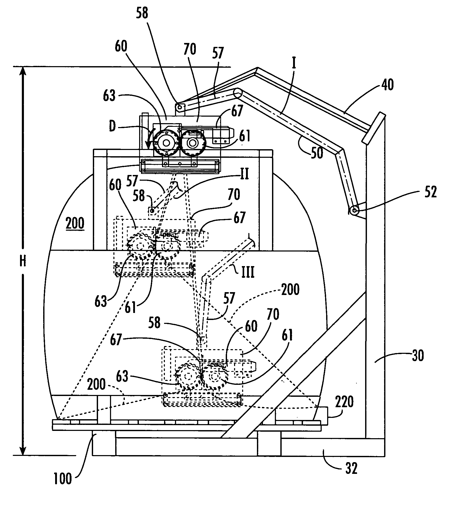
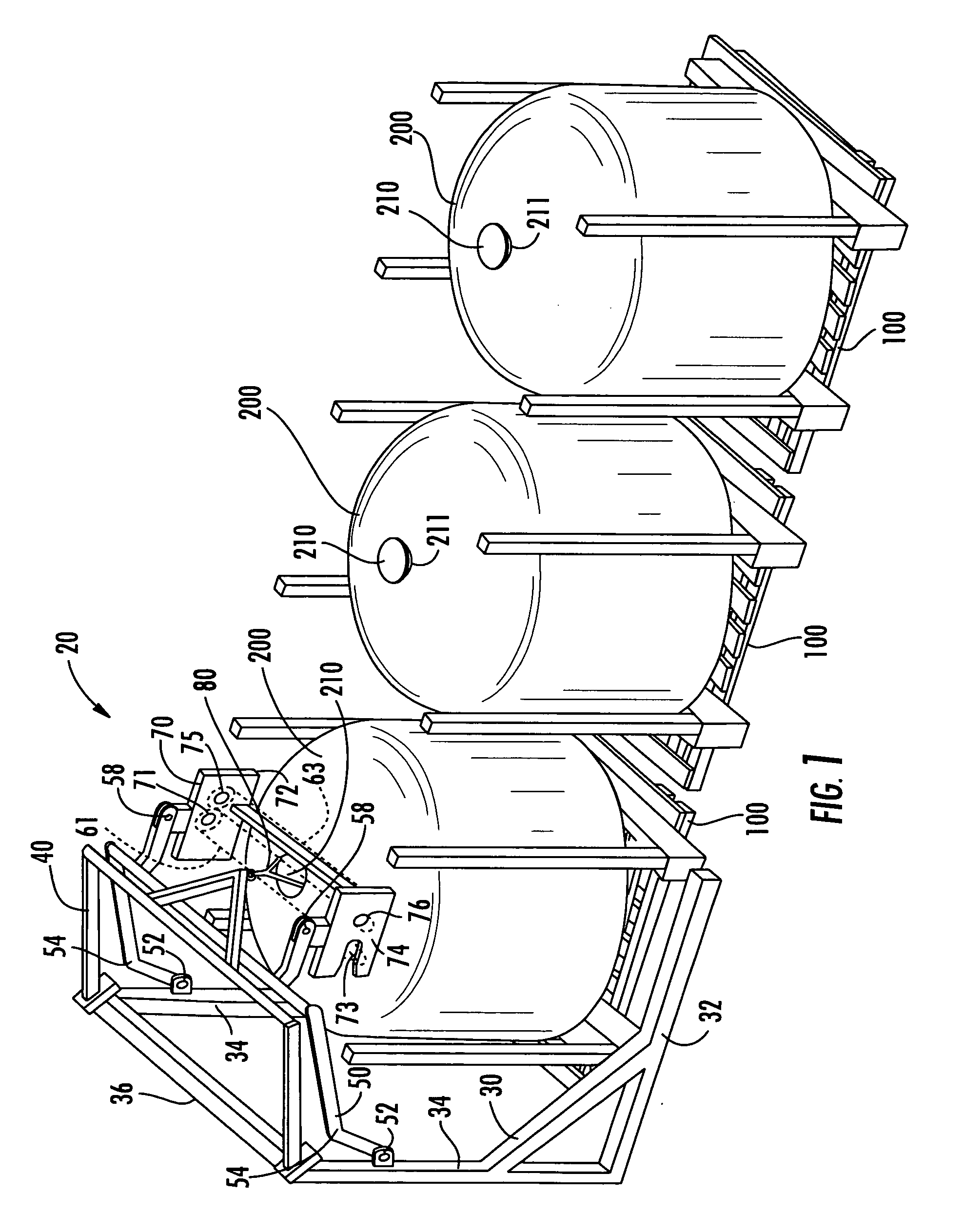
[0042] The present invention, e.g., a first embodiment, provides for a dispensing device 10 that has a support structure 20. Like reference numerals will be used for like elements. The support structure 20 may be positioned about a pallet 100 that supports a flexible container 200. More than one flexible container 200 may be positioned in a queue for emptying by the dispensing device 10. One such flexible container is the FLUID-BAG FLEXI™ container provided by Fluid-Bag Ltd. of Bottenviksvägen 54-56, FI-68600 Jakobstad, Finland.

[0043] As shown in FIG. 1, a support 30, has a base 32 supported on the ground. Extending generally in an orthogonal direction away from the base 32 are upright members 34. A cross member 36 may connect the upright members 34 to form an upright portion of the support 30. A support extension 40 is attached to an upper end of the support 30 and may support a holder 80 at a distal end of the support extension 40. The holder 80 may be positioned on a lid 210 of t...

second embodiment

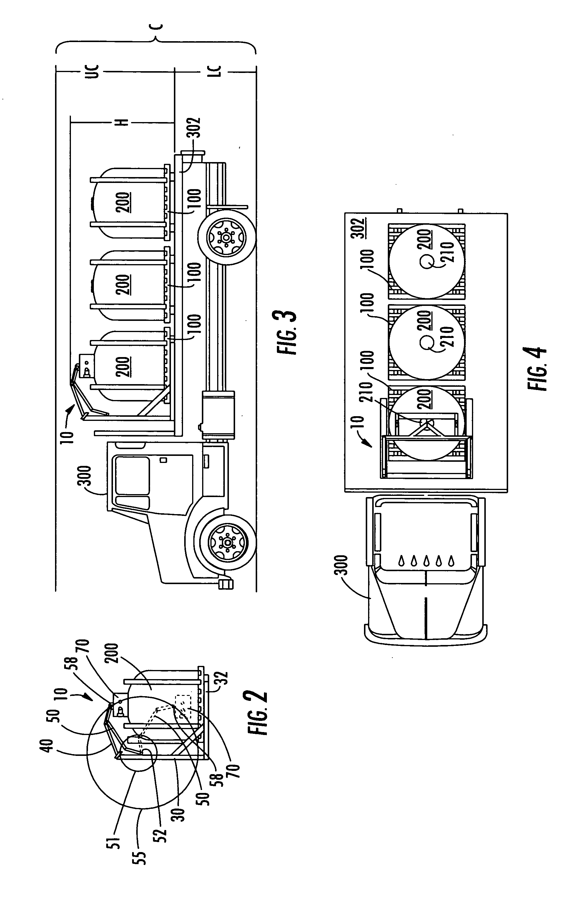
[0054]FIGS. 23-27 illustrate a dispensing device 110 having a dispensing mechanism 160 positioned on a dispensing mechanism support 170 above the flexible container 200 and supported by a support 130. More than one flexible container 200 may be positioned in a queue for emptying by the dispensing device 110. Further, the dispensing device 110 may also be mounted on a wheeled or movable transport vehicle, such as a truck, in a similar fashion as illustrated in FIGS. 3 and 4, and can be readily operated below the required clearances.

[0055] As shown in FIGS. 23, 24 and 26, the support 130 may have a base 132 and upright members 134 extending generally in an orthogonal direction away from the base 132. A cross member 136 may be provided attaching the upright members 134 of the support 130. In addition, the support 130 may also include at least one actuator 133 for manipulating a linkage 150 pivotally supported on the support 130. The actuator 133 may also be pivotally attached to linkag...


PUM


Abstract

A dispensing device and method for dispensing fluids from a flexible container is disclosed. The dispensing device includes a support and a linkage pivotally attached to the support. The dispensing device may also include a roller mechanism coupled to the linkage, wherein the roller mechanism has at least two squeeze members configured to engage a flexible container that coact with a drive roller to force the roller mechanism in a first direction to dispense fluids from a flexible container.

Description

CROSS REFERENCE TO RELATED APPLICATIONS [0001] This application claims the benefit of U.S. Provisional Patent Application No. 60 / 709,248, filed Aug. 18, 2005 and entitled “BULK TRANSFER DISPENSING DEVICE” which is hereby incorporated by reference in its entirety.BACKGROUND OF THE INVENTION [0002] 1. Field of the Invention [0003] The present invention relates to dispensing devices and methods for dispensing contents from flexible containers and, more particularly, to a dispensing apparatus and method that may be used to dispense fluids. [0004] 2. Description of Related Art [0005] Fluids, including semi-fluids, grease, friction modifying materials and other viscous materials, may be stored and shipped in flexible containers adapted to carry hundreds of pounds or more of fluid. These containers may be made from a variety of flexible materials for dispensing the fluids through an outlet of the container. One example of such a container may be found in PCT International Application No. P...

Claims


Application Information

Patent Timeline
Patent Type & Authority Applications(United States)
IPC IPC(8): B65D35/28B67D99/00
CPCB60P3/224B65B69/0091B65B69/005
Inventor BAKER, MATTHEW JASONSCHNORR, CHARLES HENRY IIIPOWELL, WARD T.URMSON, W. THOMAS JR.
Owner PORTEC RAIL PRODS
Learn More