Cutting tool with very fine adjustment

a cutting tool and adjustment technology, applied in the field of cutting tools, can solve the problems of high cost of production of fine screw threads, inability to produce finer screw threads in practice, and inability to implement at all with a high level of complication and expenditur

Inactive Publication Date: 2007-04-19
SANDVIK INTELLECTUAL PROPERTY AB
View PDF30 Cites 26 Cited by
  • Summary
  • Abstract
  • Description
  • Claims
  • Application Information

AI Technical Summary

Benefits of technology

[0010] Although the two screwthreads are not of the finest possible configuration, nonetheless a markedly finer adjustable positioning of the tool carrier relative to the main tool body is achieved.

Problems solved by technology

However, fine screwthreads are correspondingly more expensive to produce, in proportion to their respective fineness.
Finer screwthreads can scarcely be produced in practice and are to be implemented at all only with a high level of complication and expenditure.
For many situations of use therefore, the provision of a fine screwthread with a pitch of only 0.25 mm per revolution is still too coarse to easily ensure precise setting of the tool carrier relative to the main tool body.

Method used


Image

  • Cutting tool with very fine adjustment
  • Cutting tool with very fine adjustment

Examples


Embodiment Construction

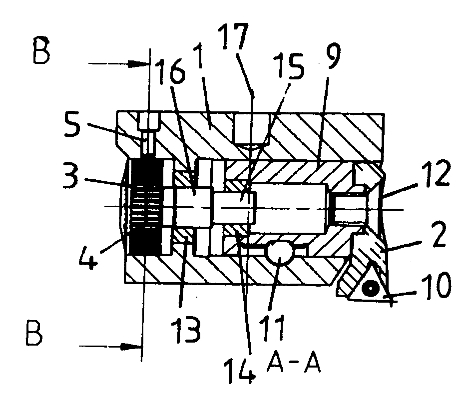
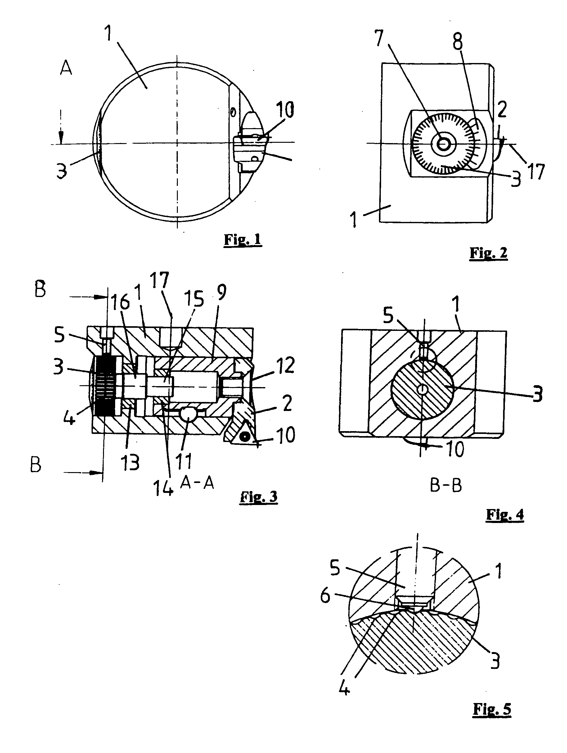
[0025]FIG. 1 shows a boring-out head from below. The boring-out head has a main tool body 1 which here is of a substantially cylindrical configuration. The boring-out head rotates about a cylinder axis 17 in operation. Fixed to the main tool body 1 is a tool carrier carrying a cutting bit 10 which in operation is in engagement with the workpiece to be machined. A spindle element 3 which is in the form of a spindle wheel can also be seen from FIG. 1. The tool carrier 2 can be adjusted in a radial direction, that is to say towards the left or the right in FIG. 1, relative to the main tool body 1.

[0026]FIG. 2 is a partial side view of the boring-out tool of FIG. 1, and shows the main tool body 1, a part of the tool carrier 2 and the spindle wheel 3. The rotary axis 17 extends perpendicularly to the axis of the spindle wheel 3. The spindle wheel 3 has a hexagonal socket, by means of which the spindle wheel 3 can be moved with the drive shaft (not shown in FIG. 2) in order to adjust the...


PUM


Abstract

A cutting tool including a main tool body and a tool carrier which is movable relative thereto for accommodating a cutting bit. The tool carrier has a screwthreaded bore co-operating with a first screwthread on a drive shaft in such a way that the tool carrier can be moved relative to the main tool body by rotation of the drive shaft. The drive shaft has a second screwthread which is arranged in a screwthreaded bore in the main tool body, such that the two screwthreads differ in respect of their pitch and/or direction of rotation.

Description

[0001] This application claims priority under 35 U.S.C. § 119 to German Patent Application No. 10 2005 045 752.5, filed on Sep. 23, 2005, the disclosure of which is incorporated by reference herein in its entirety. FIELD OF THE INVENTION [0002] The present invention relates generally to a cutting tool including a main tool body and a tool carrier which is movable relative thereto for accommodating a cutting bit, wherein the tool carrier has a screwthreaded bore co-operating with a screwthread on a drive shaft in such a way that the tool carrier can be moved relative to the main tool body by rotation of the drive shaft. BACKGROUND OF THE INVENTION [0003] Cutting tools of the type described above have long been known. For example, a boring-out tool is known which has a main tool body, at the end of which there is provided a tool carrier which is adjustable relative to the main tool body, the tool carrier being movable in the radial direction. Here the tool carrier comes into engagemen...

Claims


Application Information

Patent Timeline
Patent Type & Authority Applications(United States)
IPC IPC(8): B23B29/00
CPCB23B29/03414Y10T82/2585B23B2260/088B23B2260/056
Inventor FRANK, PETERNEUMANN, JENS
Owner SANDVIK INTELLECTUAL PROPERTY AB
Why Eureka
Try Eureka