

Methods and Apparatus for Expanding Tubular Members
a tubular member and expansion method technology, applied in the direction of fluid removal, borehole/well accessories, mining structures, etc., can solve the problems of tubular weakened, failure, and decrease in the thickness of the material forming the tubular,
- Summary
- Abstract
- Description
- Claims
- Application Information
AI Technical Summary
Benefits of technology
Problems solved by technology
Method used
Image

Examples
Embodiment Construction
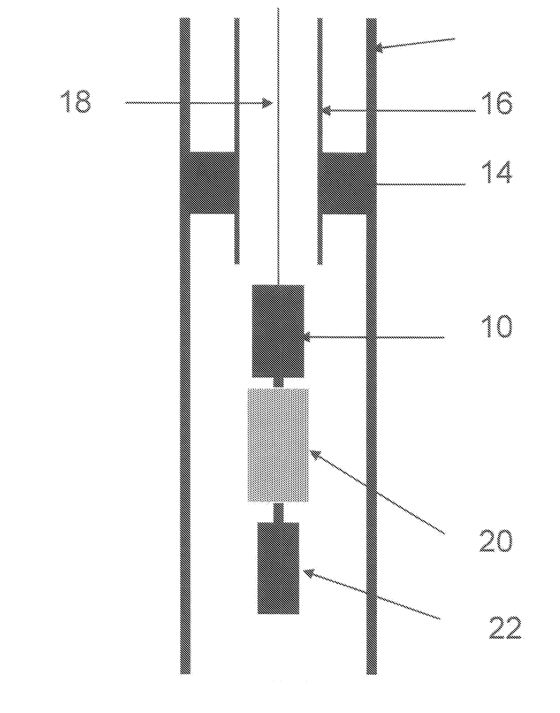
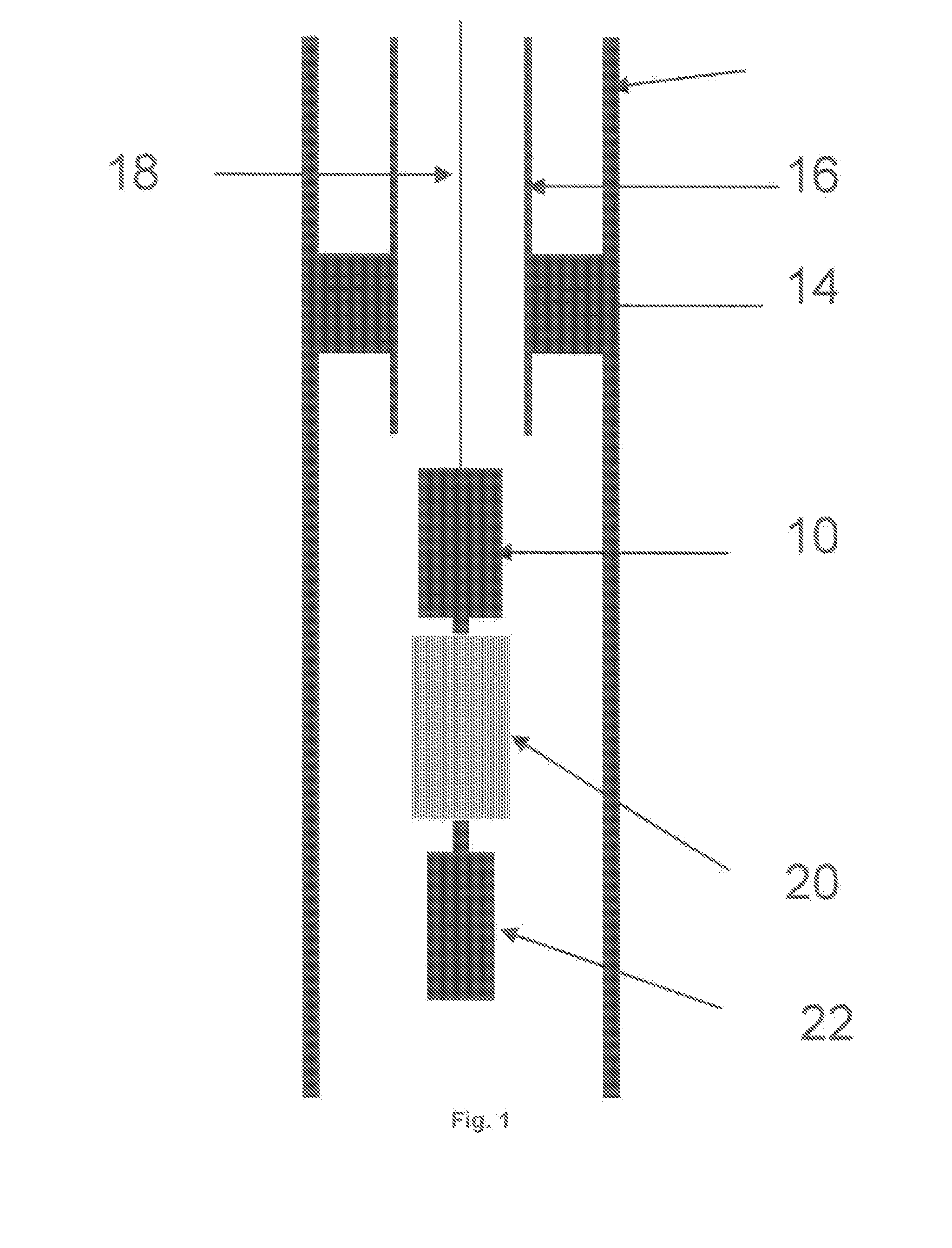
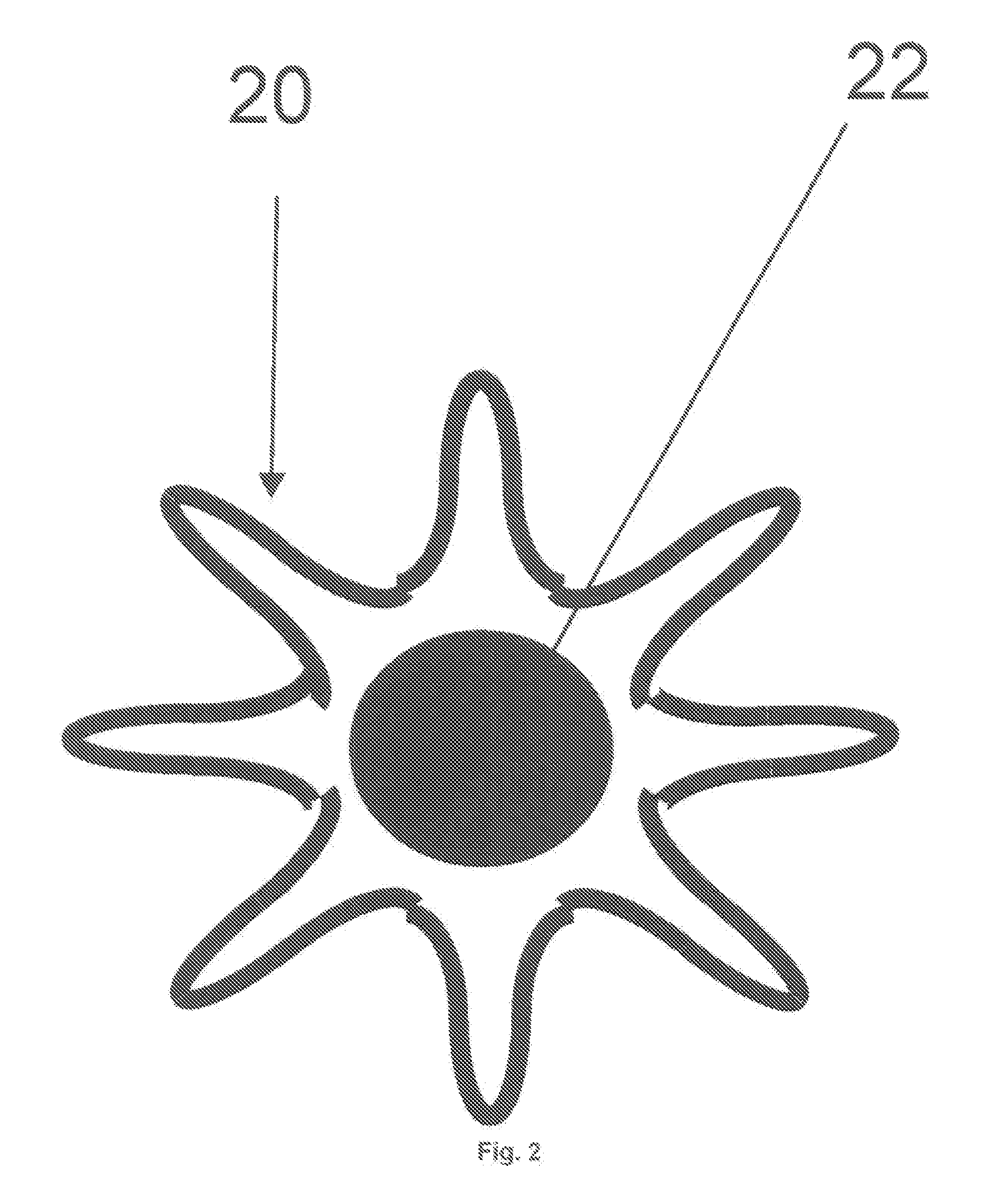
[0041] The fundamentals of expandable tubular in wells are well-known and will not be described in detail here. One such application comprises the expansion of a sleeve inside a casing to close off perforations that might be producing water. The use of an embodiment of the invention in such an application is shown schematically in FIG. 1. In use, a tool 10 according to one embodiment of the invention, is positioned in a well 12 through production tubing 16 located in the well 12 by means of a packer 14 and extending to the surface (not shown). The tool 10 is lowered through the tubing 16 by means of a wireline cable 18 which provides electric power and data to the tool 10. An expandable sleeve 20 is positioned on the tool 10 with a mandrel 22 positioned below the sleeve 20 and connected to the tool 10 through the centre thereof. In this example, the sleeve 20 is vertically corrugated as is shown in FIG. 2 so as to reduce its outer diameter and allow its installation through tubing. ...
PUM
 Abstract
Description
Claims
Application Information