Eureka AIR delivers breakthrough ideas for toughest innovation challenges, trusted by R&D personnel around the world.

Circuit breaker common inter-phase link

Inactive Publication Date: 2007-04-19
EATON CORP
View PDF6 Cites 0 Cited by
  • Summary
  • Abstract
  • Description
  • Claims
  • Application Information

AI Technical Summary

Benefits of technology

[0016] These needs, and others, are met by the present invention which provides an inter-phase link structured to operatively couple two or more telecommunication system circuit breakers. The inter-phase link is a component of a shared tripping device that also includes a trip

Problems solved by technology

Thus, while the conventional components of a telecommunication system circuit breaker may not be unique, the necessity of having a reduced size requires specialized configurations and robust components that are different than power distribution circuit breakers.
This is especially true where the telecommunication system circuit breakers are used in environments wherein the circuit breaker may be expected to operate for over 10,000 operating cycles and 50 tripping cycles; however, the reduced size telecommunication system circuit breakers are typically limited to a current rating of 30 amps.
In smaller circuit breakers which have a low trip force, the use of a common trip bar is not feasible.

Method used


Image

  • Circuit breaker common inter-phase link
  • Circuit breaker common inter-phase link
  • Circuit breaker common inter-phase link

Examples


Embodiment Construction

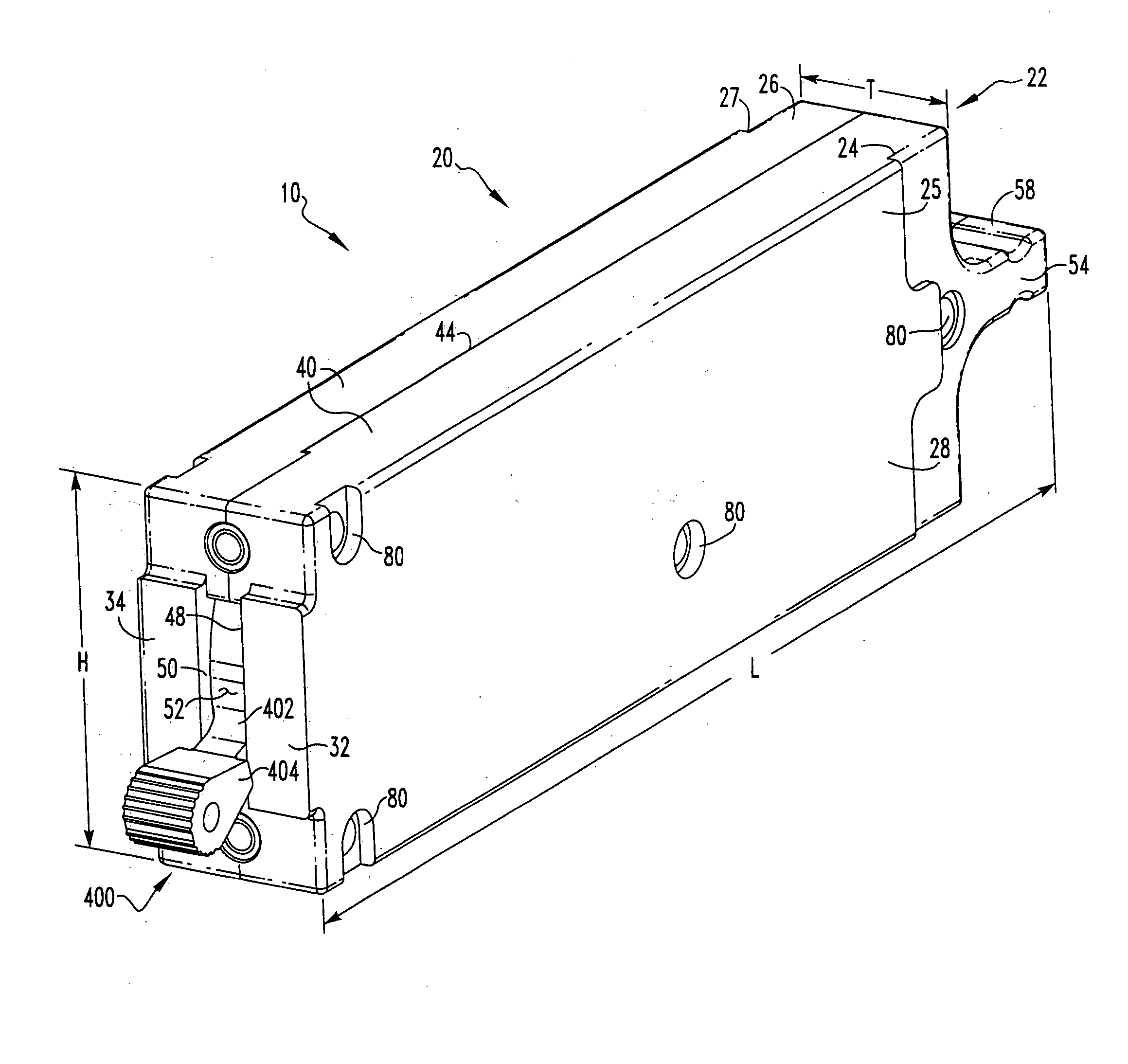
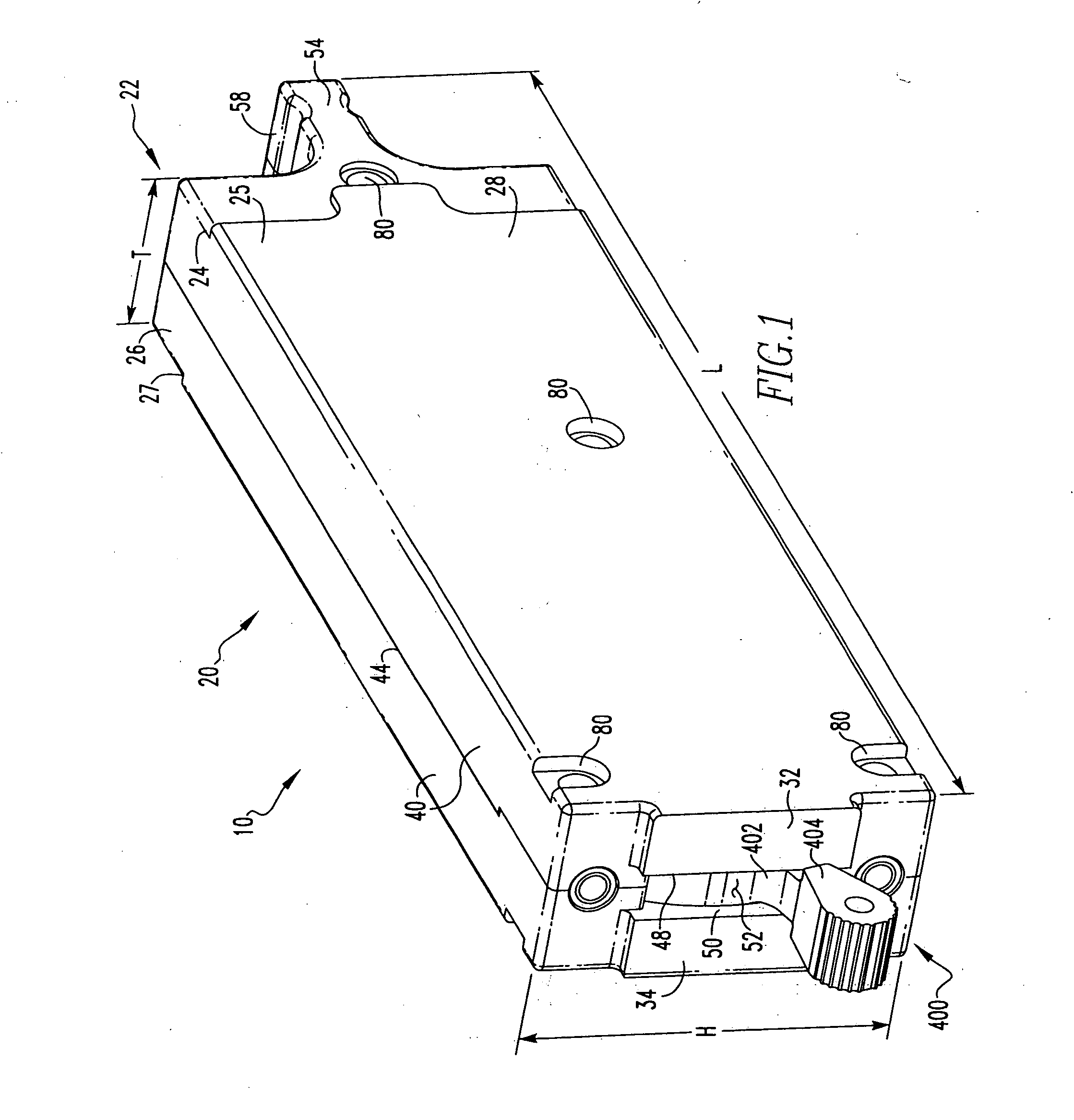
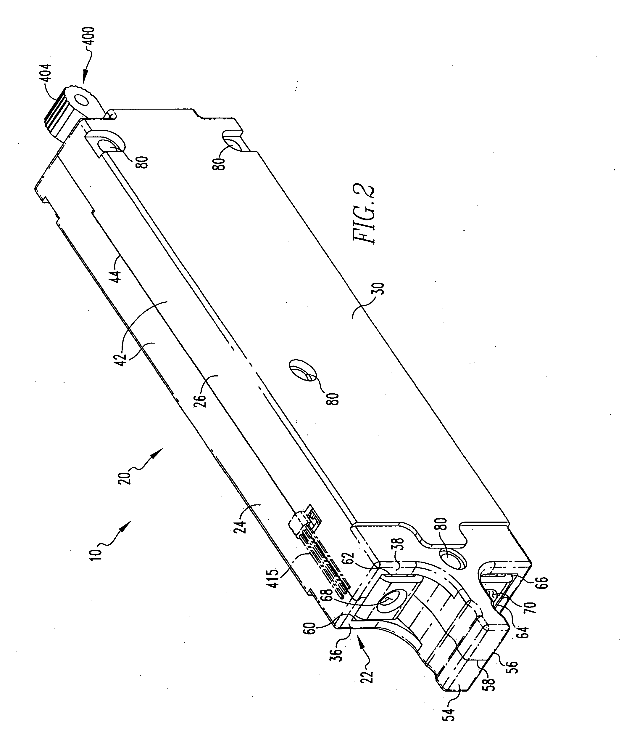
[0044] As used herein, directional terms, such as “vertical,”“horizontal,”“left,”“right”, “clockwise,” etc. relate to the circuit breaker 10 as shown in most of the Figures, that is, with the handle assembly 400 located at the left side of the circuit breaker 10 (FIG. 5), and are not limiting upon the claims.

[0045] The present invention is disclosed in association with a telecommunication system circuit breaker 10, although the invention is applicable to a wide range of circuit breakers for a wide range of applications such as but not limited to residential or molded case circuit breakers.

[0046] As shown in FIGS. 1-4, a circuit breaker 10 includes a housing assembly 20, a current path assembly 100 (FIG. 3), an operating mechanism 200, a trip device 300, and a handle assembly 400. Generally, the current path assembly 100 includes a pair of separable contacts 105 (FIG. 3) including a first, fixed contact 100 and a second, movable contact 120. The movable contact 120 is structured to...


PUM


Abstract

An inter-phase link for a shared tripping device, wherein the shared tripping device is structured to operatively couple at least two circuit breakers, and the inter-phase link has an elongated body with a mounting end and a distal end. The inter-phase link body mounting end is structured to be coupled to the primary circuit breaker operating mechanism and the inter-phase link body distal end is structured to extend through a primary circuit breaker housing assembly shaped opening and a secondary circuit breaker housing assembly shaped opening to engage the secondary circuit breaker trip device.

Description

CROSS-REFERENCE TO RELATED APPLICATIONS [0001] This application is related to commonly assigned, concurrently filed: [0002] U.S. patent application Ser. No. ______, filed ______, 2005, entitled “CIRCUIT BREAKER INCLUDING LINE CONDUCTOR HAVING BEND PORTION TO INCREASE CONTACT GAP” (Attorney Docket No. 05-EDP-280); [0003] U.S. patent application Ser. No. ______, filed ______, 2005, entitled “CIRCUIT BREAKER INTERMEDIATE LATCH” (Attorney Docket No. 05-EDP-281); [0004] U.S. patent application Ser. No. ______,filed ______, 2005, entitled “ELECTRICAL SWITCHING APPARATUS INCLUDING OPERATING MECHANISM HAVING INSULATING PORTION” (Attorney Docket No. 05-EDP-282); [0005] U.S. patent application Ser. No. ______,filed ______, 2005, entitled “AUXILIARY SWITCH INCLUDING MOVABLE SLIDER MEMBER AND ELECTRIC POWER APPARATUS EMPLOYING SAME” (Attorney Docket No. 05-EDP-285); [0006] U.S. patent application Ser. No. ______,filed ______, 2005, entitled “CONTACT ARM WITH 90 DEGREE OFFSET” (Attorney Docket N...

Claims


Application Information

Patent Timeline
IPC IPC(8): H01H9/00
CPCH01H71/1018H01H71/1027
Inventor ZINDLER, MARK O.
Owner EATON CORP
Why Eureka
Eureka Blog
Learn More