Flat cable bending holder
a flat cable and bending technology, applied in the direction of contact members penetrating/cutting insulation/cable strands, cable arrangements between relatively moving parts, applications, etc., can solve the problem of difficult next work, inability to use conventional flat cable fixtures, and inability to stably hold bent shapes. problems, to achieve the effect of stably holding bent shapes and easy and proper bending of flat cables
- Summary
- Abstract
- Description
- Claims
- Application Information
AI Technical Summary
Benefits of technology
Problems solved by technology
Method used
Image

Examples
first embodiment
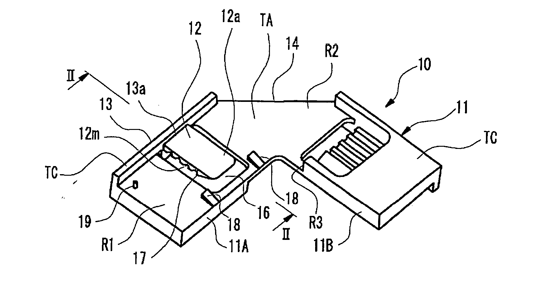
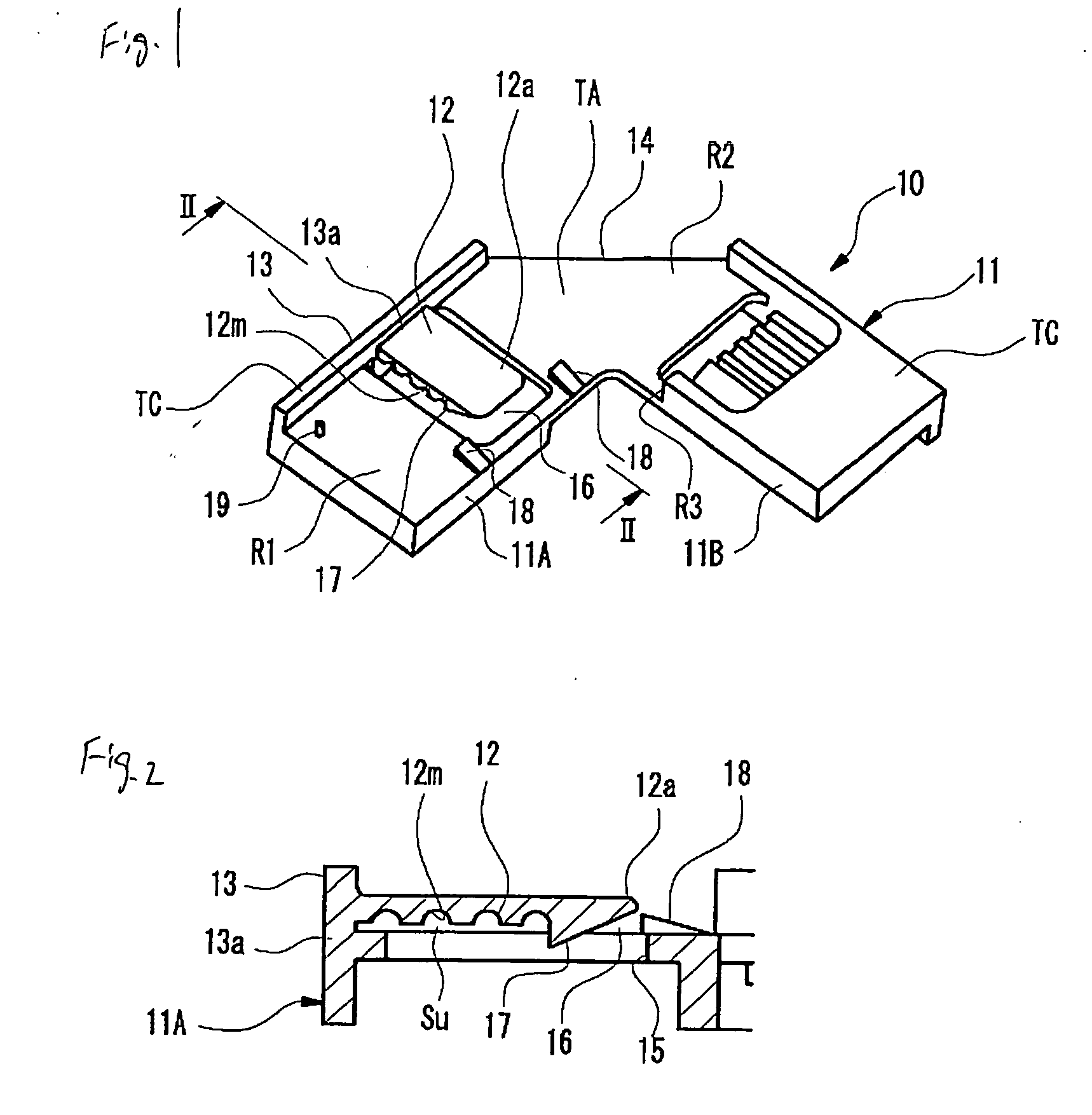
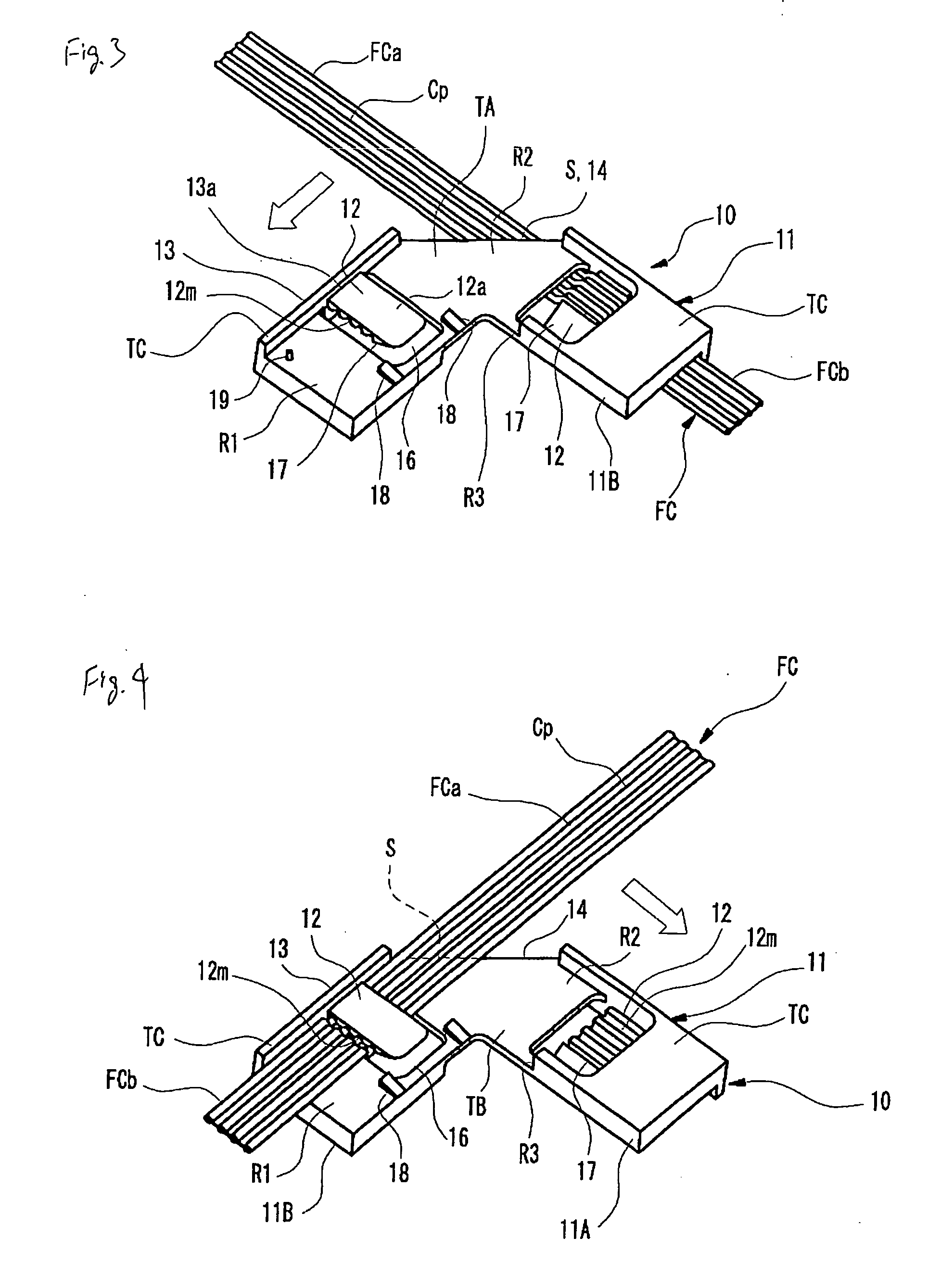
[0092] FIGS. 1 to 6 show a flat cable bending holder according to a first embodiment, wherein FIG. 1 is a perspective view showing the flat cable bending holder viewed from the front surface thereof, FIG. 2 is a cross-sectional view taken along line II-II of FIG. 1, FIG. 3 is a perspective view showing a state that a flat cable is provided on the rear surface of the bending holder, viewed from the front surface thereof, FIG. 4 is a perspective view showing the state of FIG. 3 viewed from the rear surface thereof, FIG. 5 is a perspective view showing a state that the flat cable is being bent on the front surface of the bending holder as a next operation of FIG. 3, viewed from the front surface thereof, and FIG. 6 is a perspective view showing a state that bending is finished on the bending holder, viewed from the front surface thereof.
[0093] As shown in FIG. 1, the flat cable bending holder 10 is a monolithically molded product made of plastic and includes a plate 11, holding pieces...
second embodiment
[0113]FIG. 7 is a perspective view showing the configuration of a flat cable bending holder according to a second embodiment and FIG. 8 is a perspective view showing a state that the flat cable is set in the bending holder.
[0114] The bending holder 10B according to the second embodiment is different from the bending holder 10 according to the first embodiment in that the lengths of the left and right sleeve portions 11A and 11B increase and tape-winding concave portions TK for winding tapes on the flat cables FCa and FCb together with the sleeve portions 11A and 11B are provided at the ends of the holding pieces 12 of the sleeve portions 11A and 11B, respectively. Since the other configurations are the same as the first embodiment, the same components are denoted by the same reference numerals and thus their description will be omitted.
[0115] In the case where the tape-winding concave portions TK are provided, it is possible to securely wind the tapes TP at proper positions when w...
third embodiment
[0116] FIGS. 9 to 14 show a flat cable bending holder according to a third embodiment, wherein FIG. 9 is a perspective view showing the flat cable bending holder viewed from the front surface thereof, FIG. 10 is a cross-sectional view taken along line X-X of FIG. 9, FIG. 11 is a perspective view showing a state that a flat cable is provided on the rear surface of the bending holder, viewed from the front surface thereof, FIG. 12 is a perspective view the state of FIG. 11 viewed from the rear surface thereof, FIG. 13 is a perspective view showing a state that the flat cable is being bent on the front surface of the bending holder as a next operation of FIG. 11, viewed from the front surface thereof, and FIG. 14 is a perspective view showing a state that bending is finished on the bending holder, viewed from the front surface thereof.
[0117] A bending holder 10C according to the third embodiment is different from the bending holder 10 according to the first embodiment in that the hold...
PUM
 Abstract
Description
Claims
Application Information
 - Generate Ideas
- Intellectual Property
- Life Sciences
- Materials
- Tech Scout
- Unparalleled Data Quality
- Higher Quality Content
- 60% Fewer Hallucinations
Browse by: Latest US Patents, China's latest patents, Technical Efficacy Thesaurus, Application Domain, Technology Topic, Popular Technical Reports.
© 2025 PatSnap. All rights reserved.Legal|Privacy policy|Modern Slavery Act Transparency Statement|Sitemap|About US| Contact US: help@patsnap.com