Battery holding structure for vehicle

a technology for holding structures and batteries, applied in the direction of machine supports, furniture parts, other domestic objects, etc., can solve the problems of battery damage, mechanics need to perform troublesome work, battery damage,

Active Publication Date: 2006-03-21
KAWASAKI MOTORS LTD
View PDF15 Cites 49 Cited by
  • Summary
  • Abstract
  • Description
  • Claims
  • Application Information

AI Technical Summary

Benefits of technology

[0013]Accordingly, it is an object of the present invention to provide a battery holding structure for a vehicle, facilitating work for holding a battery on the vehicle, and capable of fastening a battery to the vehicle in a short time and of firmly holding a battery on the vehicle.

Problems solved by technology

Therefore, the mechanic needs to perform a troublesome work for supporting the hook rod by one of the hands and placing the clamping plate on the battery by the other hand.
The floor panel of the working vehicle, in particular, is at a low height from the ground and hence the mechanic unavoidably needs to stoop during most part of the troublesome work, which puts a considerable workload on the mechanic.
The battery may be damaged if the nuts are tightened excessively and the battery may unstably held and rattle if the nuts are tightened insufficiently.

Method used


Image

  • Battery holding structure for vehicle
  • Battery holding structure for vehicle
  • Battery holding structure for vehicle

Examples


Embodiment Construction

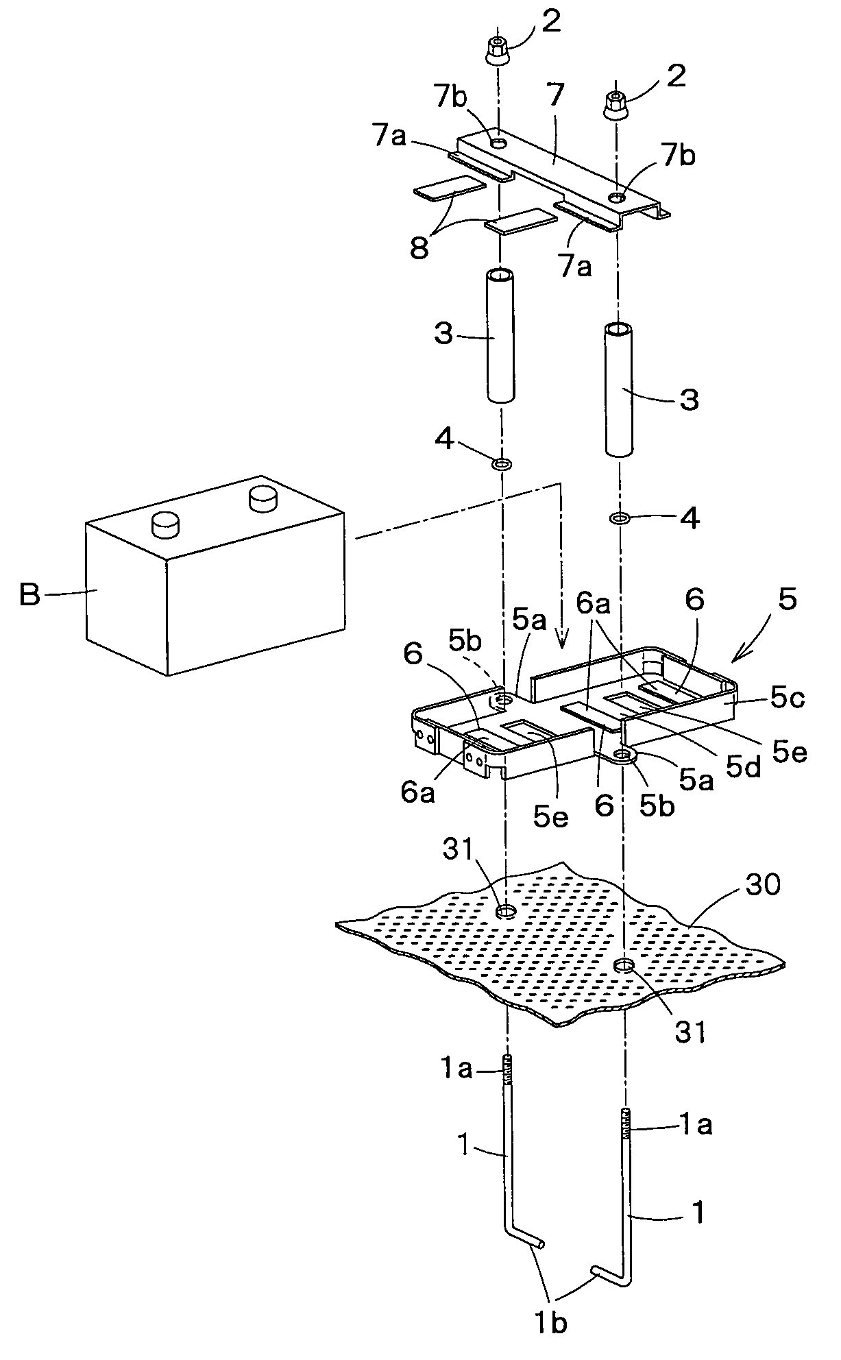
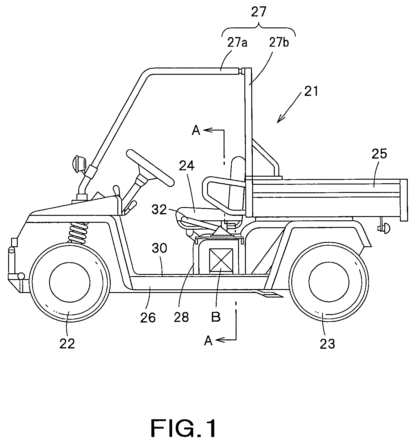
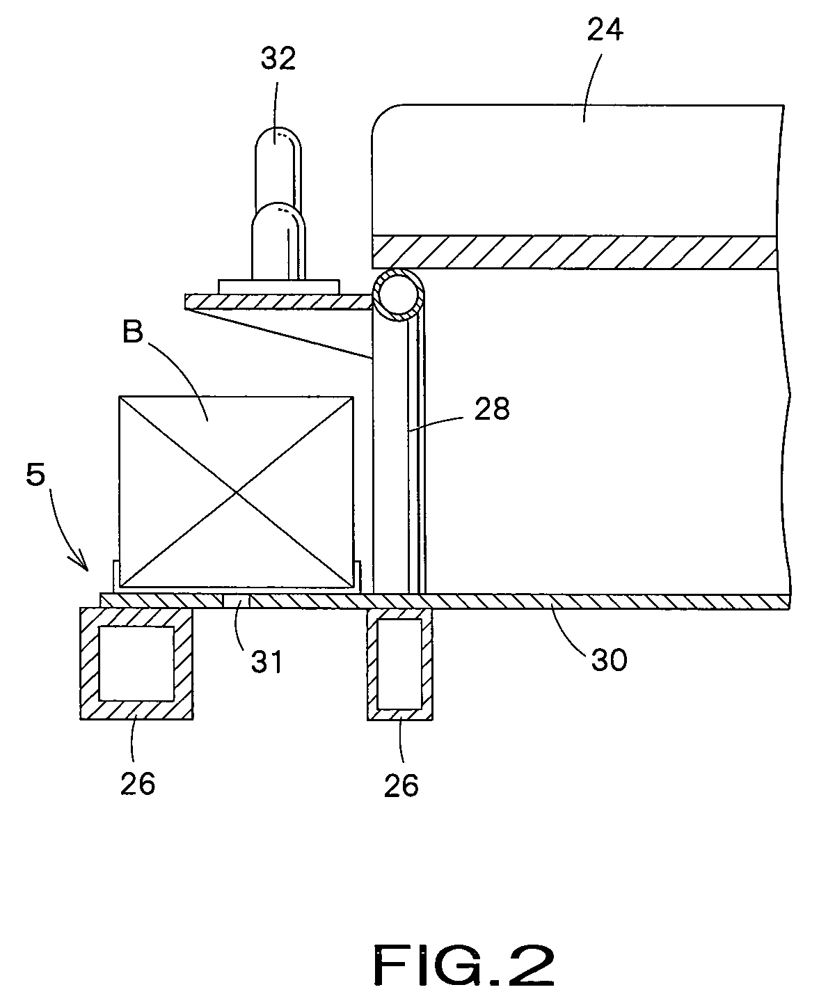
[0029]FIG. 1 is a side elevation of a utility vehicle provided with a battery holding structure in a preferred embodiment according to the present invention, FIG. 2 is a sectional view taken on the line A—A in FIG. 1, FIG. 3 is an exploded perspective view of the battery holding structure embodying the present invention and FIG. 4 is a fragmentary, longitudinal sectional view of the battery holding structure shown in FIG. 3 holding a battery on a vehicle. Referring to FIG. 1, a utility vehicle 21 has a body frame 26 formed by assembling metal members, four wheels, namely, two front wheels 22 and two rear wheels 23, a driver's seat 24, a cabin frame 27, and a load carrying platform 25. More specifically, the front wheels 22 are suspended from a front part of the body frame 26, the rear wheels 23 are suspended from a rear part of the body frame 26, the driver's seat 24 is disposed behind the front wheels 22, and the load carrying platform is disposed behind the driver's seat 24 . . . ...


PUM


Abstract

Since the battery is placed in the battery tray, the battery can stably held in place even if the battery support part of the floor panel is somewhat uneven. The battery support part (31) on which the battery (B) is supported is a part of a floor panel (30) of the vehicle (21), the number of the mounting holes (31) is at least two, the battery is placed in a battery tray (5) placed on the battery support part, the battery tray has lugs (5a) provided with holes (5b) having a diameter greater than that of the hook rods (1) and smaller than an outside diameter of the tubular spacers (3) at positions corresponding to the mounting holes, and the battery tray (5) is fastened together with the battery (B) to the battery support part (31) of the floor panel through the tubular spacers by the hook rods.

Description

BACKGROUND OF THE INVENTION[0001]1. Field of the Invention[0002]The present invention relates to a battery holding structure for holding a battery on a vehicle and, more particularly, to a battery holding structure suitable for holding a battery on a utility vehicle.[0003]2. Description of the Related Art[0004]Utility vehicles are those suitable for various kinds of work including carrying goods on rough roads. Generally, a utility vehicle 21 as shown in FIG. 1 has a body frame 26 formed by assembling metal parts, four wheels, namely, two front wheels 22 and two rear wheels 23, a power unit, not shown, such as an engine, a driver's seat 24, and a load carrying platform 25 disposed behind the driver's seat 24. In most cases, the wheels 22 and 23 are provided with wide tires suitable for running on rough roads.[0005]In most cases, a battery mounted on the utility vehicle 21 is used not only as a power source for starting, ignition and control of the engine, illumination and lighting m...

Claims


Application Information

Patent Timeline
Patent Type & Authority Patents(United States)
IPC IPC(8): B60R16/04
CPCB60R16/04
Inventor MIZUTA, FUMIO
Owner KAWASAKI MOTORS LTD
Why Eureka
Try Eureka