
Conduit clamping device

Inactive Publication Date: 2007-04-26
BURLISON AARON
View PDF27 Cites 1 Cited by
  • Summary
  • Abstract
  • Description
  • Claims
  • Application Information

AI Technical Summary

Problems solved by technology

If the vise jaws are further tightened in an effort to hold the conduit motionless, they may crush or deform or otherwise damage the conduit.

Method used


Image

  • Conduit clamping device
  • Conduit clamping device
  • Conduit clamping device

Examples


Embodiment Construction

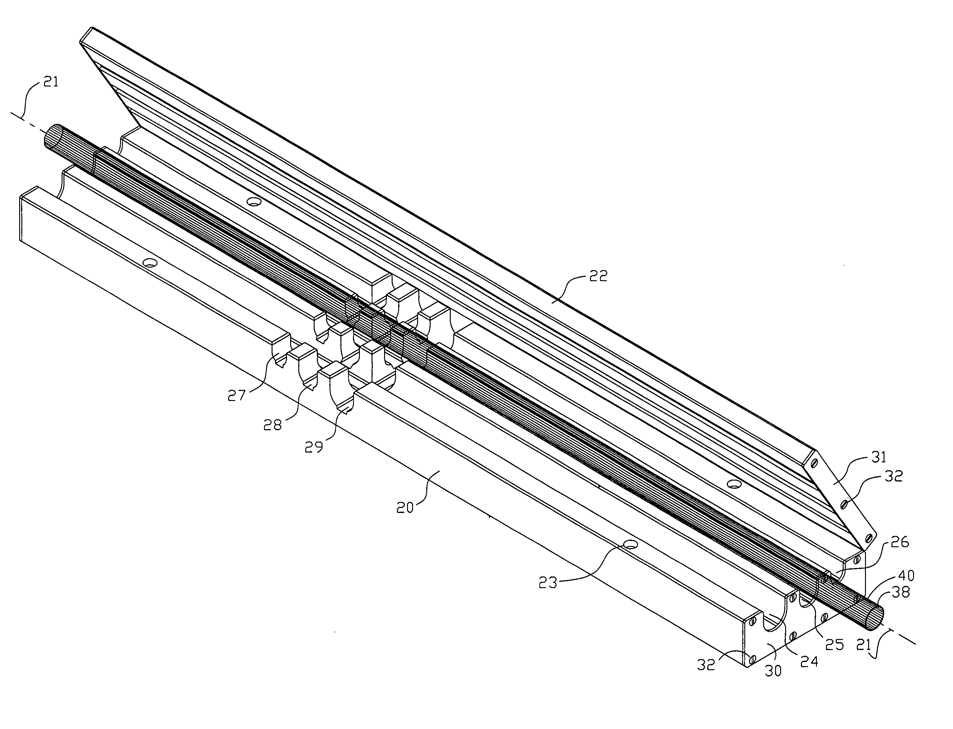
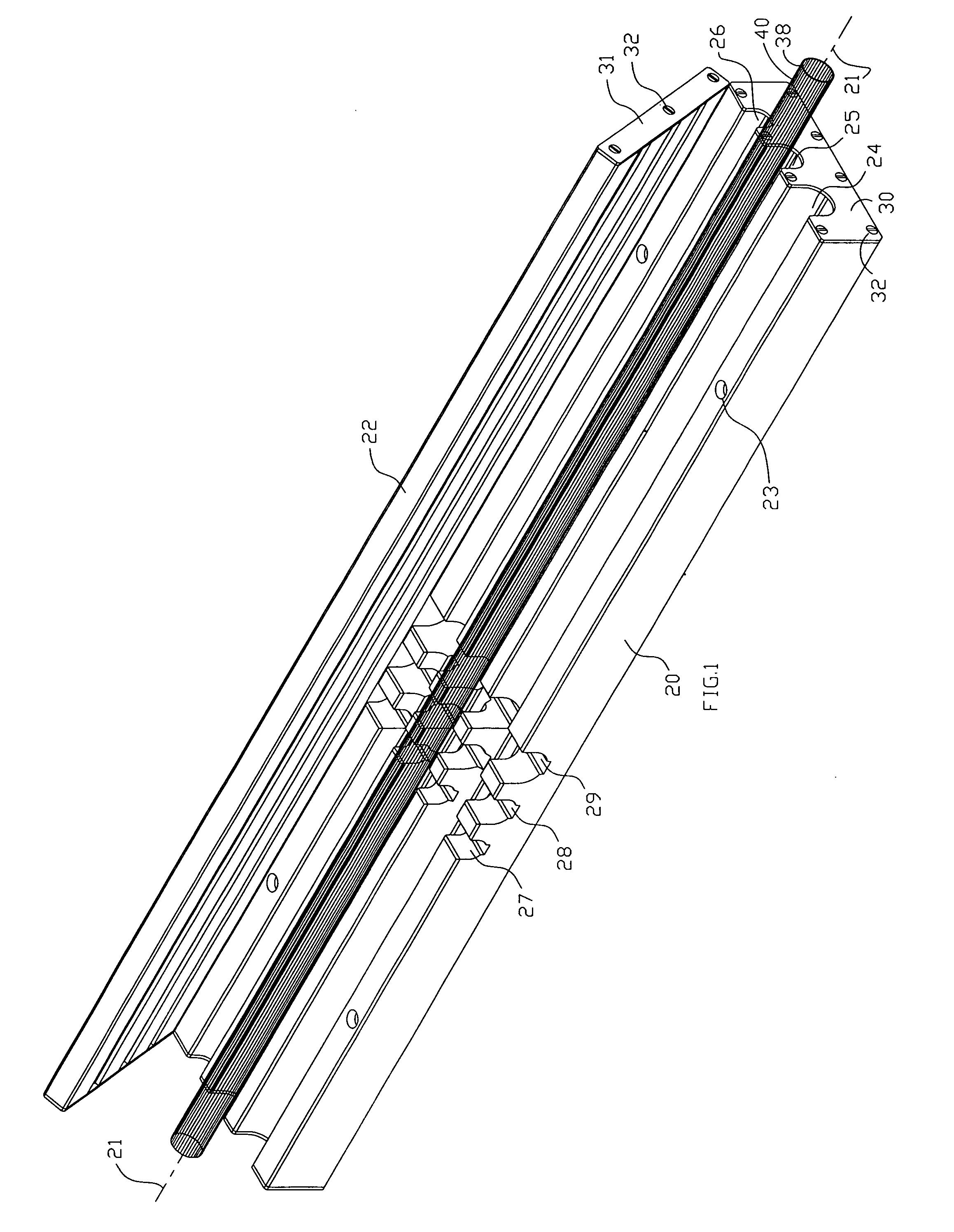
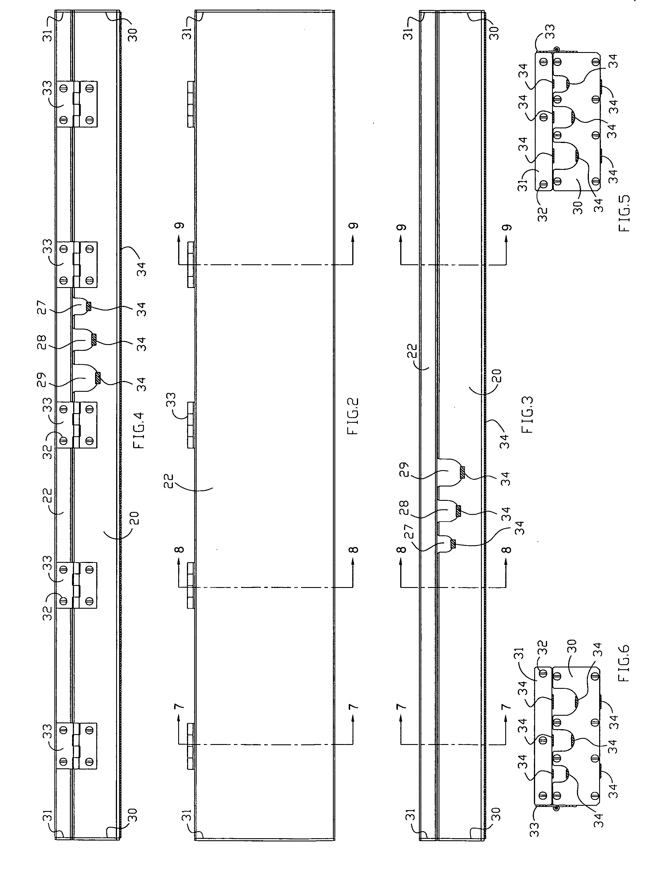
[0034] Referring to FIG. 1, there is shown a conduit clamping device in accordance with one aspect of the invention. The conduit clamping device has an elongated substantially rigid base or body portion 20 having a longitudinal axis 21. At least one axially extending elongated generally U-shaped channel (in the illustrated embodiment, three channels 24, 25, 26) is formed in the base and sized to receive at least a portion of a length of conduit, e.g., 38, of a given diameter therein. A lid 22 is hingedly coupled to the base 20 and relatively hingedly movable between a first or open position, shown in FIG. 1, for permitting conduit to be placed in or removed from the channel 24, 25 or 26 and a second or closed position (as shown in FIGS. 7-9) for grippingly engaging the conduit between the lid 22 and the channel.

[0035] Referring also to FIGS. 2-7, to further enhance the secure engagement of the conduit, a quantity of resilient material 34, such as neoprene may be mounted to at least...


PUM


Abstract

A conduit clamping device has an elongated substantially rigid base having a longitudinal axis. At least one axially extending elongated generally U-shaped channel is formed in the base and sized to receive at least a portion of a length of conduit of a given diameter. A lid is hingedly coupled to the base and relatively hingedly movable between an open position for permitting conduit to be placed in or removed from the channel and a closed position for grippingly engaging the conduit between the lid and the channel. A quantity of resilient material is mounted to at least one of the lid and the channel for resiliently, grippingly engaging the conduit when the lid is in the closed position.

Description

BACKGROUND OF THE INVENTION [0001] 1. Field of the Invention [0002] The present invention is directed to tools such as clamps, vises, and jigs and, more particularly, to a conduit clamping device. [0003] 2. Description of the Related Art [0004] Building codes commonly require that when installing 110 VAC household electrical wiring, the conductors are to be pulled through a grounded, electrically conductive metal tubing known as conduit or EMT. Typically, during construction, the conduit must be cut to various lengths, and sometimes bent at various angles in order to direct the wiring to and among desired locations. Such conduit is commonly fabricated from aluminum, steel, or the like in a variety of diameters depending on the number of conductors or wires to be pulled through the conduit. For example, conduit is typically provided in diameters of one half inch, three-quarter inch and one inch, although other sizes are possible. [0005] Typically, electricians use a manual hacksaw, o...

Claims


Application Information

Patent Timeline
IPC IPC(8): B23Q3/00
CPCB25B1/20B25B1/2405B25B5/006B25B5/147Y10S269/903
Inventor BURLISON, AARON
Owner BURLISON AARON
Learn More