Methods and apparatus for inspecting an object

a technology of light measurement system and object inspection, applied in the field of objects inspection, can solve the problems of object failure, object performance reduction, object noise, etc., and achieve the effect of facilitating inspection at least a portion

Inactive Publication Date: 2007-04-26
GENERAL ELECTRIC CO
View PDF22 Cites 33 Cited by
  • Summary
  • Abstract
  • Description
  • Claims
  • Application Information

AI Technical Summary

Benefits of technology

This patent describes two methods for insulating objects using special techniques involving lasers or other optics. One method involves shining light into the eye of an individual through a liquid crystal display screen, which then reflects back out after being altered in some way. By measuring this reflection, researchers hope to better analyze the health of the person's eyes. Another technique uses multiple frames of light that are shifted in time to create a more complex image. These images can be used to detect flaws or defects in materials like glass or metal. Overall, these methods may improve the accuracy and efficiency of inspecting objects for quality control purposes.

Problems solved by technology

The technical problem addressed in this patent is how to improve the accuracy and reliability of inspecting objects using a light measurement system, particularly when dealing with complex shapes and surfaces that have high levels of reflection.

Method used


Image

  • Methods and apparatus for inspecting an object
  • Methods and apparatus for inspecting an object
  • Methods and apparatus for inspecting an object

Examples


Embodiment Construction

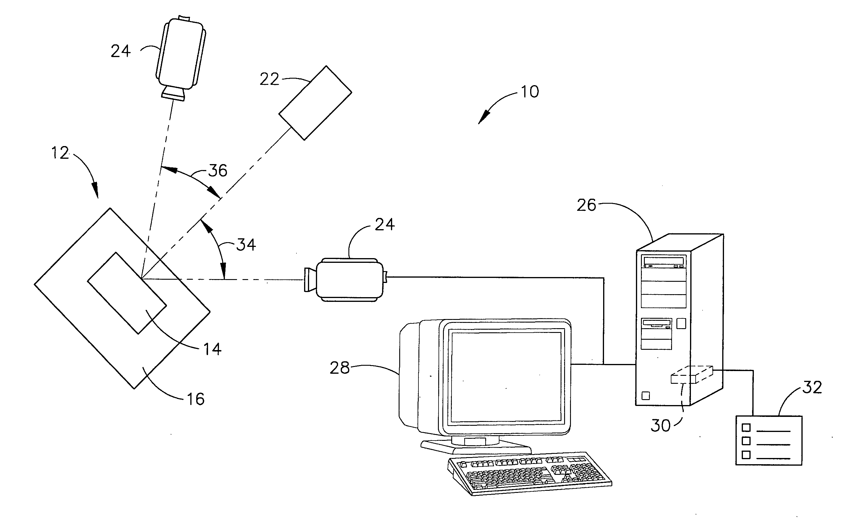
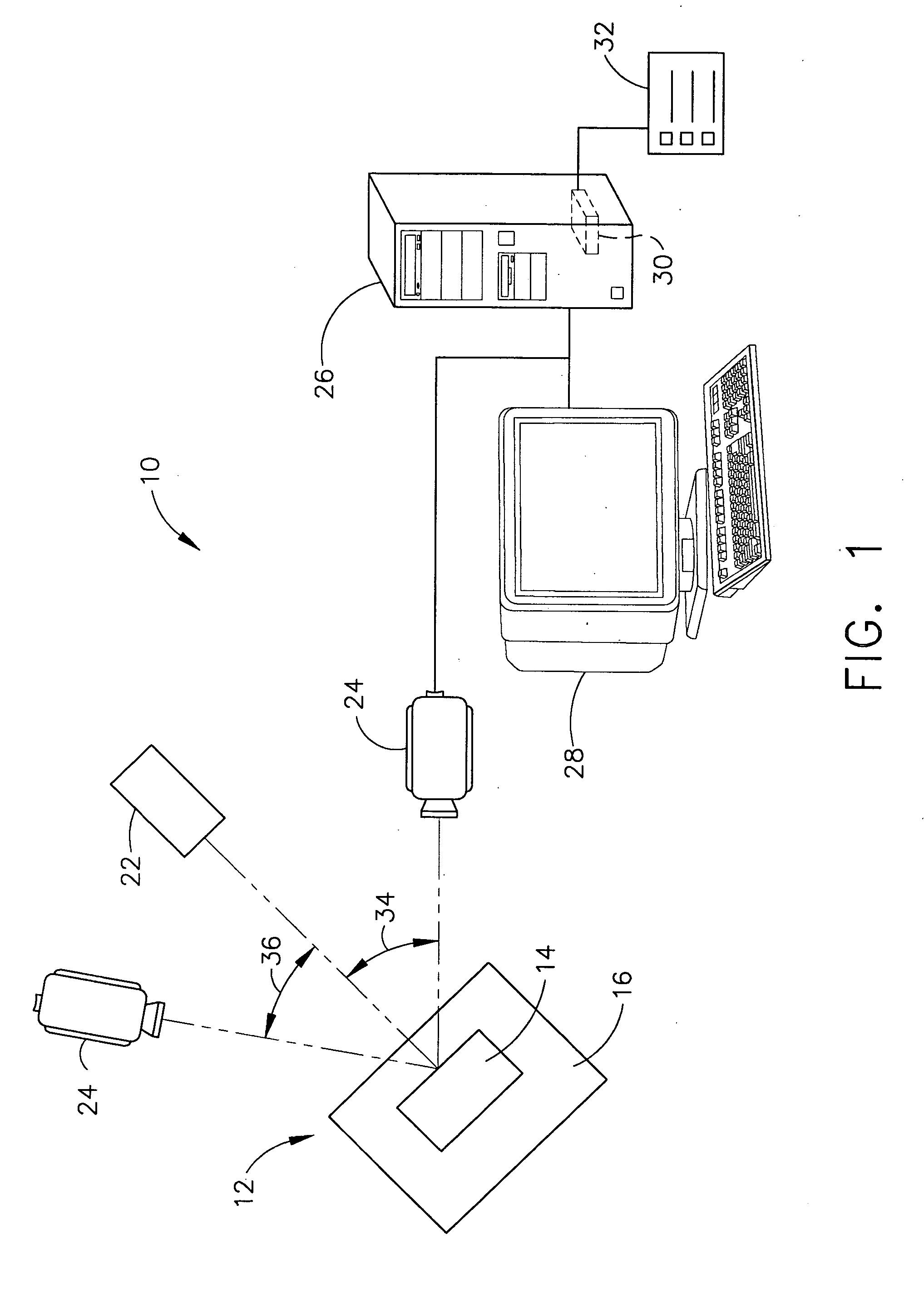
[0010]FIG. 1 is a block diagram of an exemplary embodiment of a structured light measurement system 10 that is used to measure a plurality of surface features of an object 12. For example, system 10 may be used to inspect and determine surfaces of object 12, wherein the surfaces may include features such as tilts, bends, twists, and / or warps when compared to a model representative of object 12.

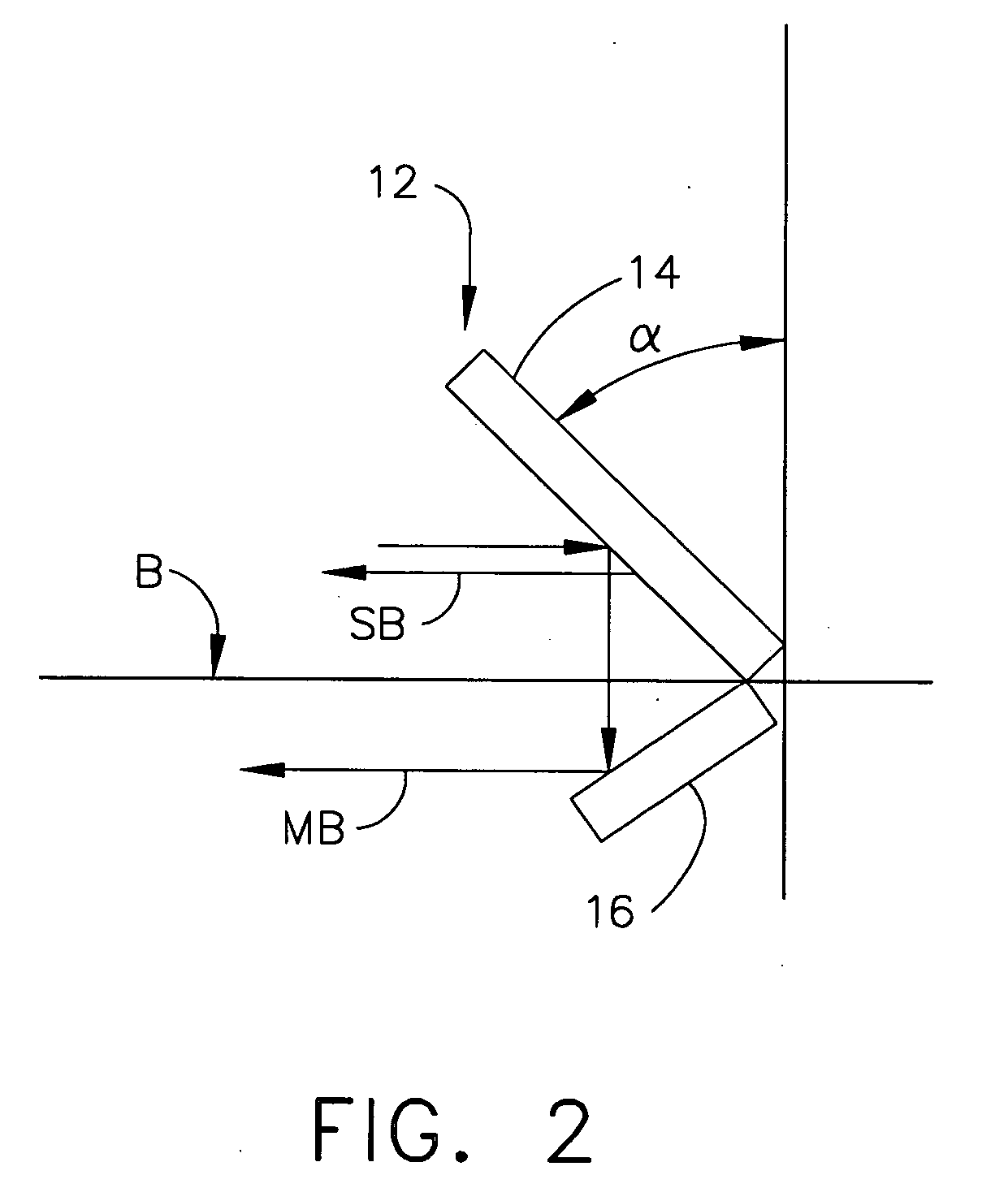
[0011] In the exemplary embodiment, object 12 is a rotor blade, such as, but not limited to, a compressor or a turbine blade utilized in a turbine engine. Accordingly, and in the exemplary embodiment, object 12 includes an airfoil 14 extending outwardly from a platform 16. While the following description is directed to inspecting gas turbine engine blades, one skilled in the art will appreciate that inspection system 10 may be utilized to improve structured light imaging for any object.

[0012] System 10 also includes a structured light source 22 that is a liquid crystal display (LCD) projecto...


PUM


Abstract

A method for inspecting an object includes emitting light from at least one of a liquid crystal display (LCD) device and a liquid crystal on silicon (LCOS) device, phase-shifting light emitted from at least one of the LCD device and the LCOS device, projecting the phase-shifted light onto a surface of an object, receiving light reflected from the object surface with an imaging sensor, and analyzing the light received by the imaging sensor to facilitate inspecting at least a portion of the object.

Description


Claims


Application Information

Patent Timeline
Owner GENERAL ELECTRIC CO
Why Eureka
Try Eureka