Solvent assisted burnishing of pre-underfilled solder bumped wafers for flipchip bonding

a technology of integrated circuit chip and underfilled solder, which is applied in the direction of thin material processing, semiconductor/solid-state device details, semiconductor devices, etc., can solve the problems of fluxless attach potential, achieve the effect of reducing assembly cost, improving interconnect reliability, and simplifying the flip-chip assembly process

Inactive Publication Date: 2007-01-30
3M INNOVATIVE PROPERTIES CO
View PDF22 Cites 120 Cited by
  • Summary
  • Abstract
  • Description
  • Claims
  • Application Information

AI Technical Summary

Benefits of technology

[0014]The present invention provides a new way to simplify the flip-chip assembly process and enables the use of a broader range of materials thereby reducing assembly cost and improving interconnect reliability.

Problems solved by technology

Additionally, the above-described method offers the potential for fluxless attach due to the scrubbing action of the bumps as they deform in the bonding process.

Method used


Image

  • Solvent assisted burnishing of pre-underfilled solder bumped wafers for flipchip bonding
  • Solvent assisted burnishing of pre-underfilled solder bumped wafers for flipchip bonding
  • Solvent assisted burnishing of pre-underfilled solder bumped wafers for flipchip bonding

Examples


example one

Comparative, Dry Abrading

[0072]A piece of silicon measuring approximately 2×2 inches and comprising an array of 9×9 bumped chips was used. The solder bumps were approximately 100 microns in diameter and were of a eutectic 63-37 Sn—Pb alloy. Each chip contained 68 bumps in a peripheral array. The chips were pre-encapsulated, using a heat-lamination process, with an uncured one-part epoxy based adhesive film having an initial thickness slightly greater than 100 microns.

[0073]The pre-encapsulated wafer-section was attached bumped side-up to an aluminum puck which was then placed face down into a Struers Metallurgical polishing machine, available from Struers, Inc. of Westlake, Ohio. The 8 in. diameter turntable was provided with a single piece of 1200 grit Emory paper. The wafer-section was placed in contact with the Emory paper with a total force of 5N. The turntable and the wafer section were spun independently at 150 rpm for a period of 35 s with no applied lubricant.

[0074]After the...

example 2

Comparative, Plasma Etching

[0075]A single chip was laminated with an uncured one-part epoxy based adhesive film. The chip contained solder bumps of roughly 100 micron diameter. The adhesive was laminated by pressing by hand at a temperature of 60 degrees C. Bump locations were visible but bumps were not exposed. Plasma etching was attempted with a Model PS0524 unit from Plasma Science, an RF type system operating at 13.5 MHz and delivering a maximum power of 500 W with matching network capability. An oxygen plasma was used. The chip was placed in the middle of the plasma field, which was of a sky blue color. A maximum power in the range of 60% of full power was used, and the chip was exposed for a period of about 15 minutes. Afterwards the adhesive surface was examined with SEM. The surface appearance suggested only a small degree of etching of the adhesive matrix but minimal to no etching of the silica filler particles themselves. The bumps, which were closely examined, remained la...

example 3

Present Invention, Effect of Wiping Material

[0076]Pieces of silicon measuring approximately 0.8×0.8 inches, each comprising an array of 4×4 chips, were used. Each chip contained 88 eutectic SnPb bumps of approximately 100 micron diameter. The chip arrays were not pre-diced. Each chip array was pre-encapsulated using a heat-lamination process with an uncured one-part epoxy based adhesive film having a thickness of approximately 100 microns.

[0077]For each chip array, the clearing of encapsulant from the bump tips was attempted with one from the series of polishing pad materials listed below in Table I. The polishing pad materials are available from Struers, Inc. of Westlake, Ohio, Allied High Tech Products, Inc. of Rancho Domingo, Calif., and The Texwipe Company LLC of Upper Saddle River, N.J.

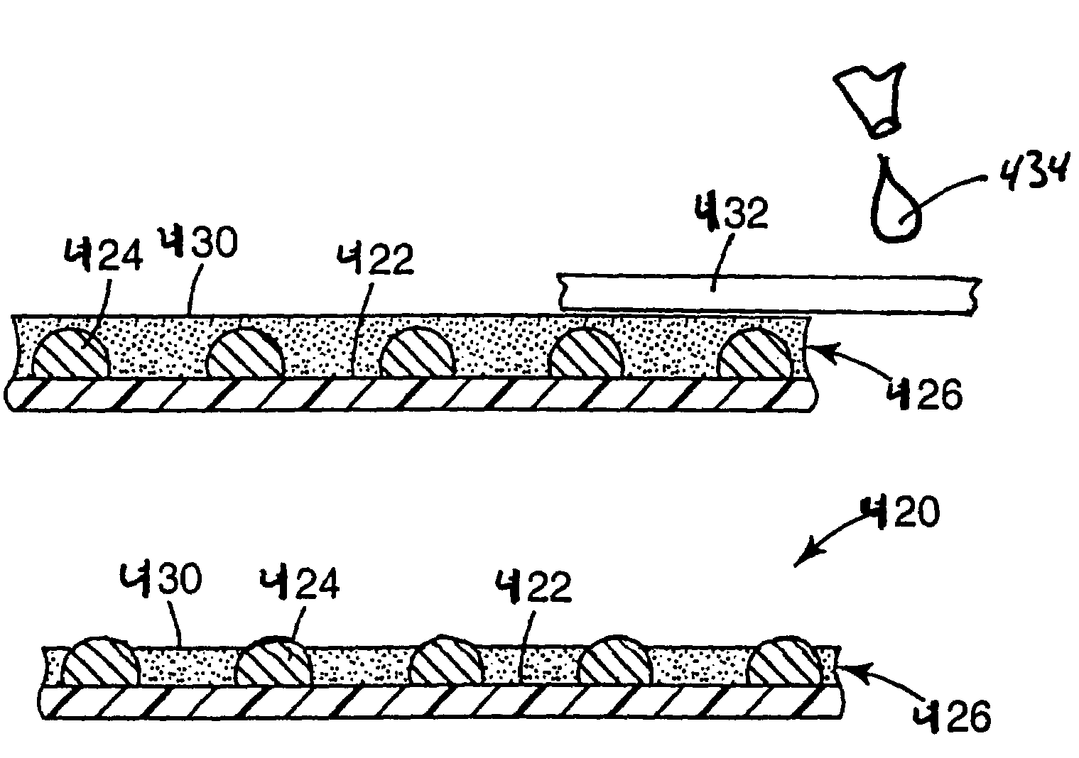
[0078]For each experiment, the polishing pad was slightly dampened with a small amount of acetone immediately prior to use. Care was taken to avoid having any standing liquid on top of the polish...


PUM

PropertyMeasurementUnit
Tgaaaaaaaaaa
viscositiesaaaaaaaaaa
diametersaaaaaaaaaa

Abstract

The present invention relates to a method for connecting an integrated circuit chip to a circuit substrate. The method includes the step of pre-applying adhesive directly to a bumped side of an integrated circuit chip. The method also includes the steps of removing portions of the adhesive from the tips of the solder bumps to expose a contact surface, and pressing the bumped side of the integrated circuit chip, which has previously been coated with adhesive, against the circuit substrate such that the bumps provide an electrical connection between the integrated circuit chip and the circuit substrate. The adhesive is removed from the tips of the solder bumps using a solvent assisted wiping action. The pre-applied adhesive on the chip forms a bond between the integrated circuit chip and the circuit substrate.

Description

[0001]This application is a continuation-in-part (CIP) of U.S. patent application Ser. No. 08 / 986,661, filed Dec. 8, 1997 now U.S. Pat. No. 6,260,264.FIELD OF THE INVENTION[0002]The present invention relates generally to methods for preparing and connecting pre-underfilled solder-bumped integrated circuit chip wafers to a circuit substrate. More specifically, the present invention relates to methods for exposing solder bumps after having laminated a highly filled adhesive film underfill to solder bumped integrated circuit chips, so that the solder bumps can make electrical connections between the integrated circuit chips and their packaging circuits.BACKGROUND OF THE INVENTION[0003]The vast majority of electronic circuit assemblies in the world today utilize integrated circuit (IC) chips which have been housed in protective packages. These packages provide mechanical and sometimes thermal protection for the chips while also providing an intermediate level of interconnection between ...

Claims


Application Information

Patent Timeline
Patent Type & Authority Patents(United States)
IPC IPC(8): H01L23/52H01L23/40H01L23/48H01L23/485H01L23/498H01L21/48H01L21/56H01L21/60
CPCH01L21/563H01L24/11H01L24/12H01L24/16H01L24/27H01L24/94H01L24/29H01L2924/00013H01L2224/13111H01L2224/81013H01L2224/29111H01L2224/2919H01L2924/1579H01L2224/81101H01L2224/81191H01L2224/73204H01L2224/73104H01L2924/0132H01L2924/014H01L2924/01033H01L2924/01006H01L2224/83101H01L24/81H01L2224/1184H01L2224/13099H01L2224/16H01L2224/274H01L2224/73203H01L2224/81205H01L2224/81801H01L2224/83191H01L2924/01005H01L2924/01013H01L2924/0105H01L2924/01074H01L2924/01079H01L2924/01082H01L2924/01322H01L2924/14H01L2924/00H01L2924/3512H01L2924/00014H01L2224/29099H01L24/83H01L2224/83856H01L2924/01025H01L2924/01057H01L2924/0781H01L2924/0665H01L2224/81012H01L2224/29019Y10T428/2857Y10T428/28Y10T29/4913Y10T29/49133H01L21/56
Inventor HOGERTON, PETER B.CHEN, KEVIN YUGERBER, JOEL A.ZENNER, ROBERT L. D.
Owner 3M INNOVATIVE PROPERTIES CO
Why Eureka
Try Eureka