Dynamic clamping device for spinal implant

a technology of clamping device and spinal column, which is applied in the field of dynamic stabilizing system of spinal column, can solve the problems that the connection of rod/screw that is suitable for metallic rods is not necessarily suitable for elastic connection elements, and achieves the effect of easy positioning and continuous operation

Inactive Publication Date: 2007-04-26
BIRD BIEDERMANN
View PDF55 Cites 101 Cited by
  • Summary
  • Abstract
  • Description
  • Claims
  • Application Information

AI Technical Summary

Benefits of technology

[0008] Accordingly, the non-positive fit rod / screw connection with a dynamic form-fit contribution allows a smooth elastic rod made of plastic material to be connected to the head of a bone or pedicle screw such that the expected forces can be transferred perma nently and securely due to its application as a dynamic stabilization of the lumbar spinal column. Thus, a non-positive fit connection, which can be positioned easily and continuously, is combined with the reliability of a form-fit contribution to the connection. In the process, the initial positive-fit is supported by a dynamic increase in the form-fit with increasing axial force, which decreases again with decreasing axial force. This takes care of the plastic rod and largely prevents the process of flowing under load.

Problems solved by technology

As a matter of principle, rod / screw connections that are suitable for metallic rods are not necessarily also suitable for elastic connection elements since elastic rods made of plastic material, for example, possess different properties than rods made of metal that are stiffer by comparison.

Method used


Image

  • Dynamic clamping device for spinal implant
  • Dynamic clamping device for spinal implant
  • Dynamic clamping device for spinal implant

Examples


Embodiment Construction

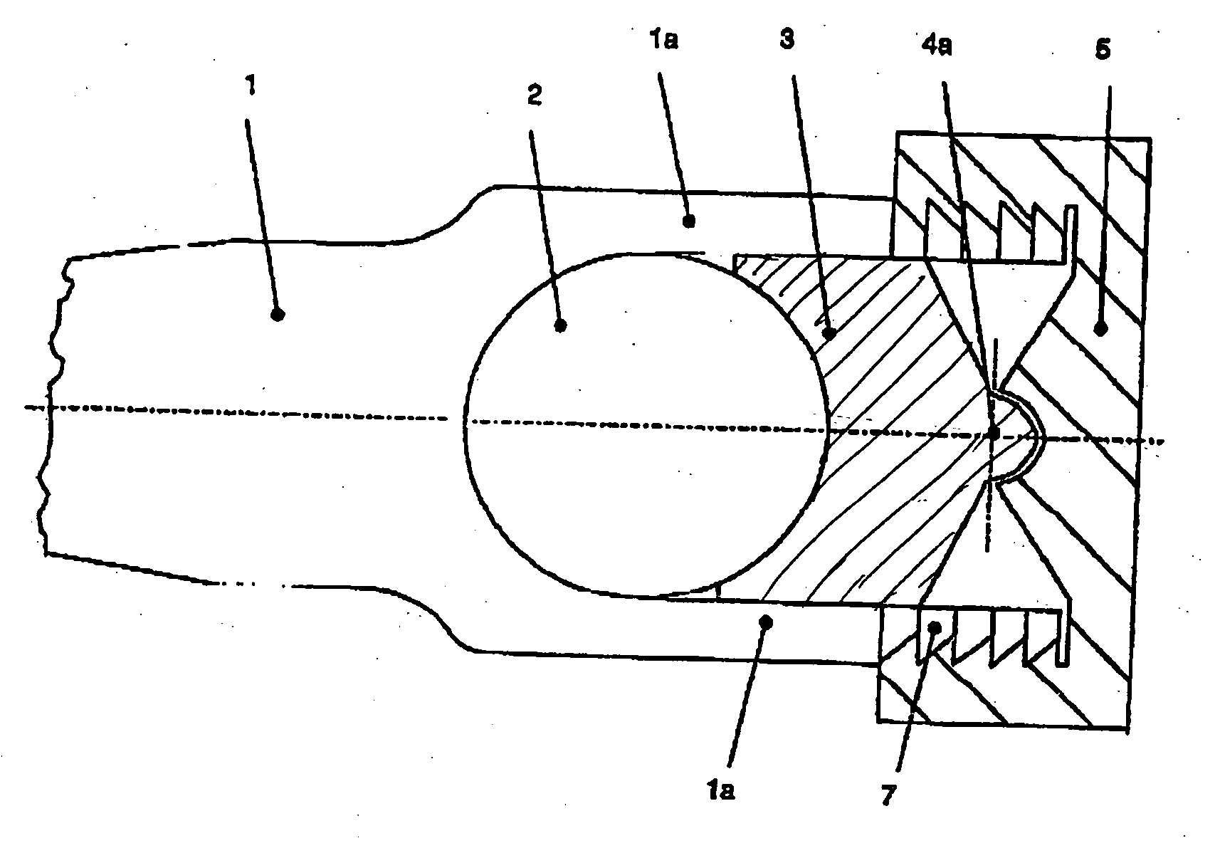
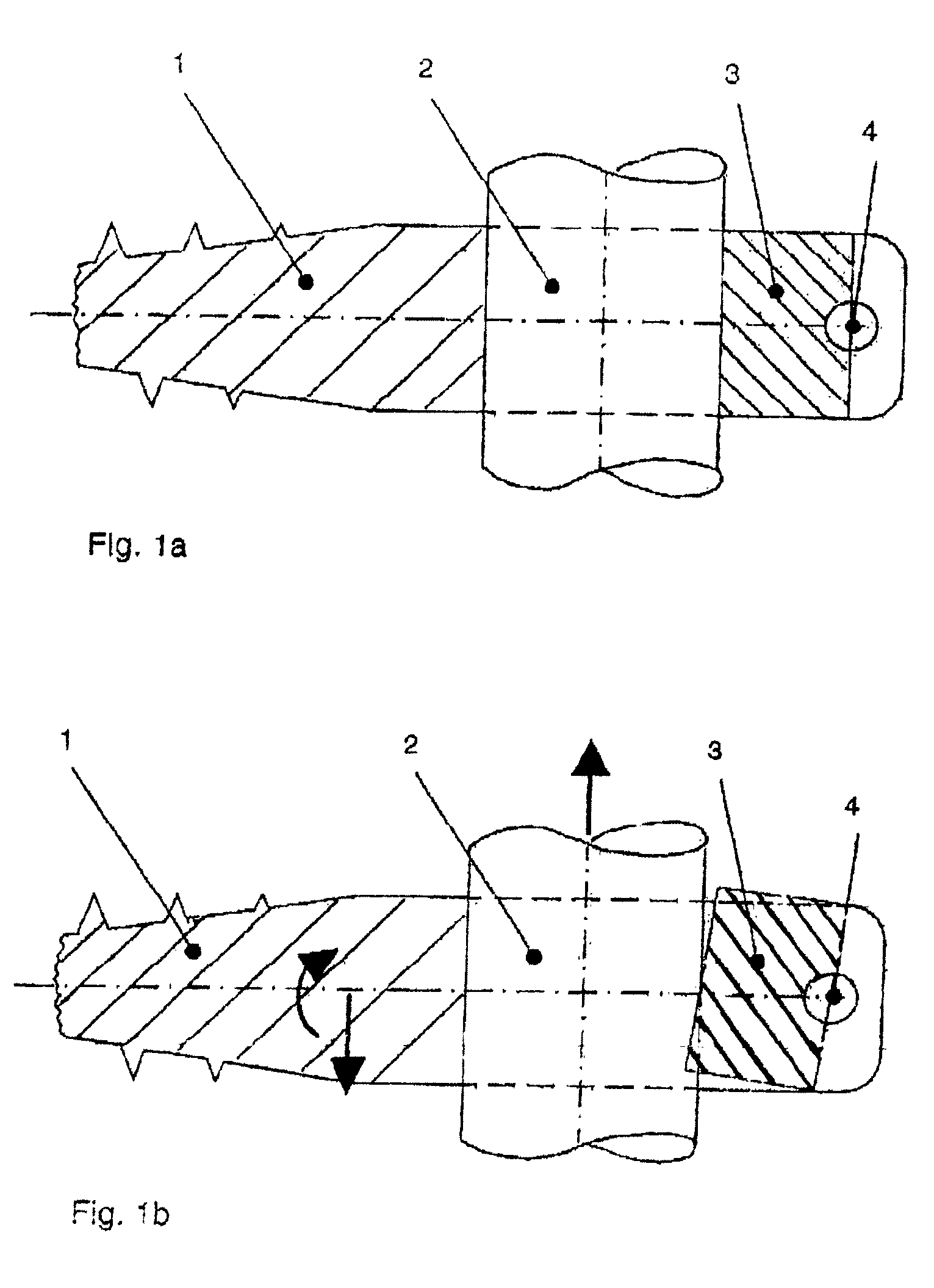
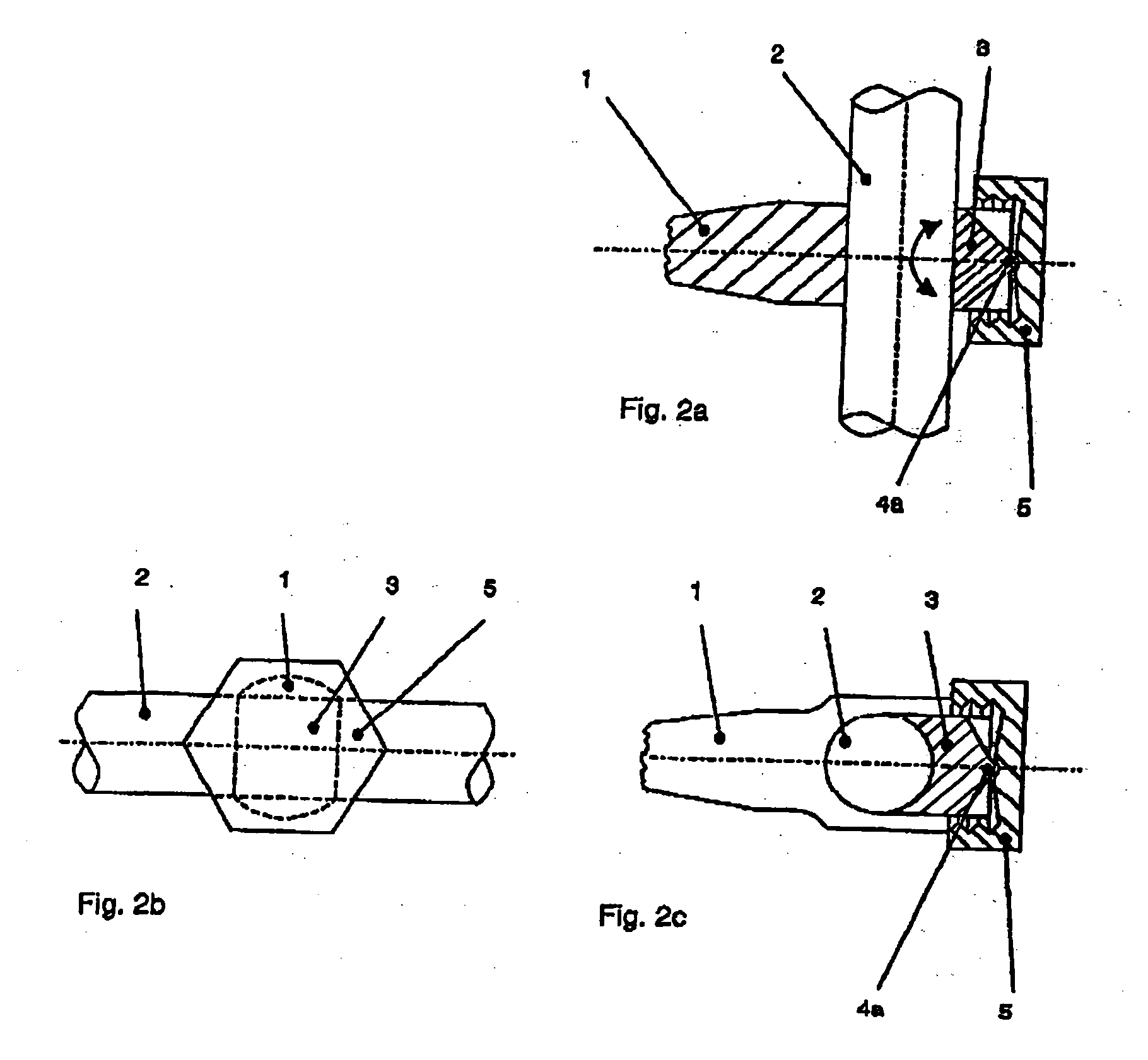
[0022]FIG. 1a shows a connection element (2) in a pedicle screw (1) (shown in cross section) with a rotatable filling piece (3) in a neutral position about a pivot point (4). The connection element (2) may be a rod of any shape. For example, the connection element can have a round cross-sectional shape. The connection element (2) is elastic and is constructed from a plastic material. An example of such a material is Polycarbonate Urethane. A clamping element (5) (shown in FIGS. 2a-2c, 3a-3c, 5 and 6) presses the filling piece (3) against the connection element (2) in a non-positive fashion, which is also referred to herein as a force-fit or a frictional fashion. FIG. 1b shows how the filling piece (3) rotates as soon as the elastic connection element (2) is exposed to tensile force or extension. The filling piece (3) is arranged such that its edge opposite to the direction of force impinges upon the surface of the elastic connection element and generates a form-fit contribution that...


PUM


Abstract

A Spinal column implant for elastic stabilization of vertebrae includes an elastic rod that is anchored in a non-positive fit fashion in the receptacle of a pedicle screws by means of a mobile filling piece and a clamping element. The non-positive fit is supported additionally by a dynamic form-fit contribution upon exposure to load.

Description

CROSS-REFERENCE TO RELATED APPLICATION(S) [0001] The present disclosure claims the benefit of U.S. Provisional Patent Application Ser. No. 60 / 738,759, filed Nov. 21, 2005, and claims priority from Swiss Patent Application 01488 / 05, filed Sep. 13, 2005, the entire disclosures of which are incorporated herein by reference.BACKGROUND [0002] The present disclosure relates to a dynamic stabilizing system for spinal columns capable of stabilizing the spinal column without spinal fusion using elastic connection elements connected to bone or pedicle screws. [0003] A multitude of rod / screw connections are available for metallic rods and used mainly in fusion operations (spinal fusion). There are only a few elastic systems that only support and stabilize, but do not fuse, the spinal segments and, thus, there are only a few devices for attaching the elastic connection elements with the pedicle screws. [0004] As a matter of principle, rod / screw connections that are suitable for metallic rods ar...

Claims


Application Information

Patent Timeline
Patent Type & Authority Applications(United States)
IPC IPC(8): A61F2/30
CPCA61B17/7032A61B17/7031
Inventor FREUDIGER, STEFAN
Owner BIRD BIEDERMANN
Why Eureka
Try Eureka