Patient Lifting Device

a lifting device and patient technology, applied in the field of patient lifting devices, can solve the problems of unsuitable for lifting patients, unsuitable for amputees without lower limbs, and people themselves can suffer back damage or back strain

a lifting device and patient technology, applied in the field of patient lifting devices, can solve the problems of unsuitable for lifting patients, unsuitable for amputees without lower limbs, and people themselves can suffer back damage or back strain

US20070094791A1Active Publication Date: 2007-05-03WALKER SIMON CHRISTOPHER DORNTON

Image

  • Patient Lifting Device
  • Patient Lifting Device
  • Patient Lifting Device

Examples


Embodiment Construction

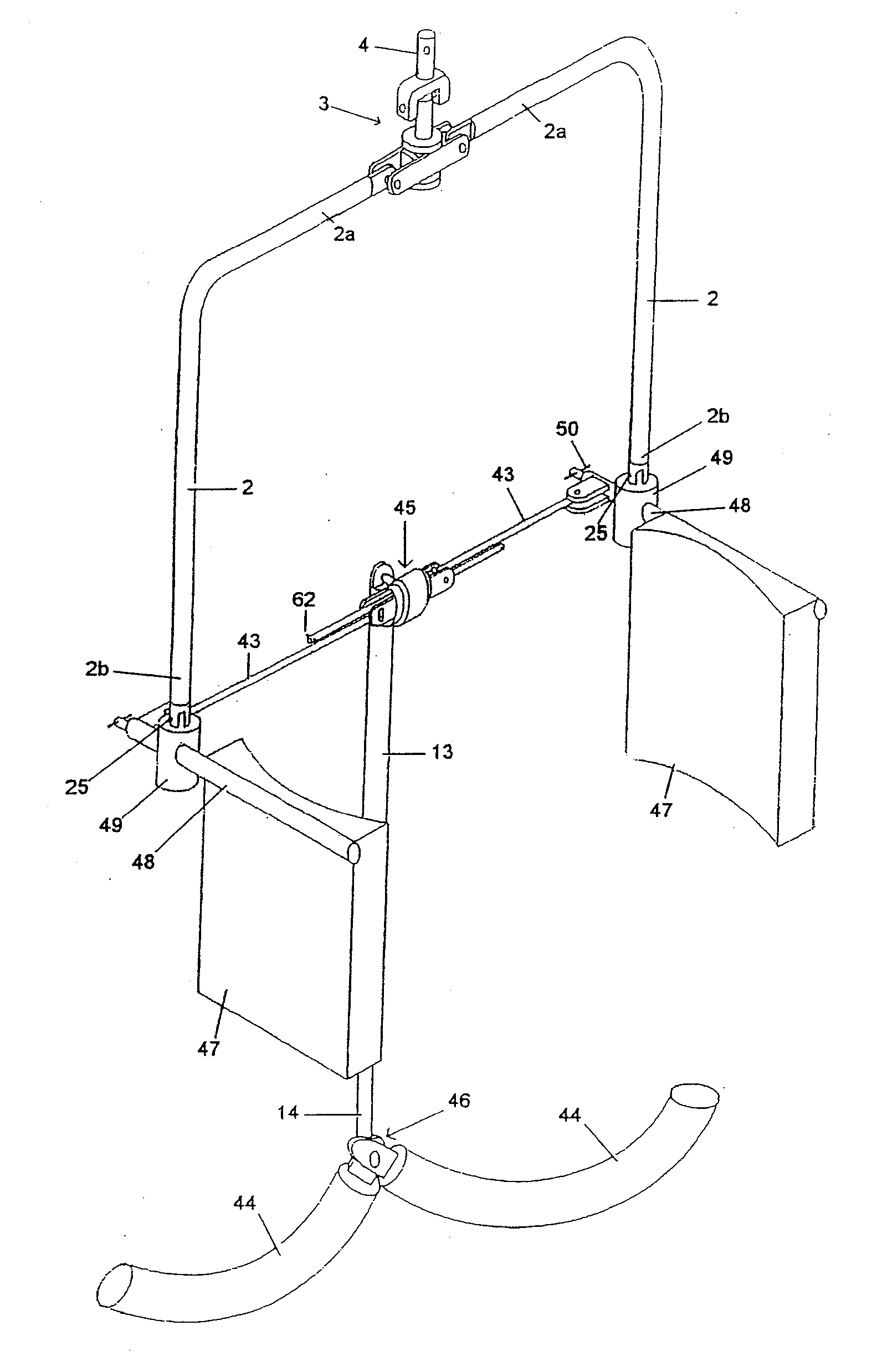
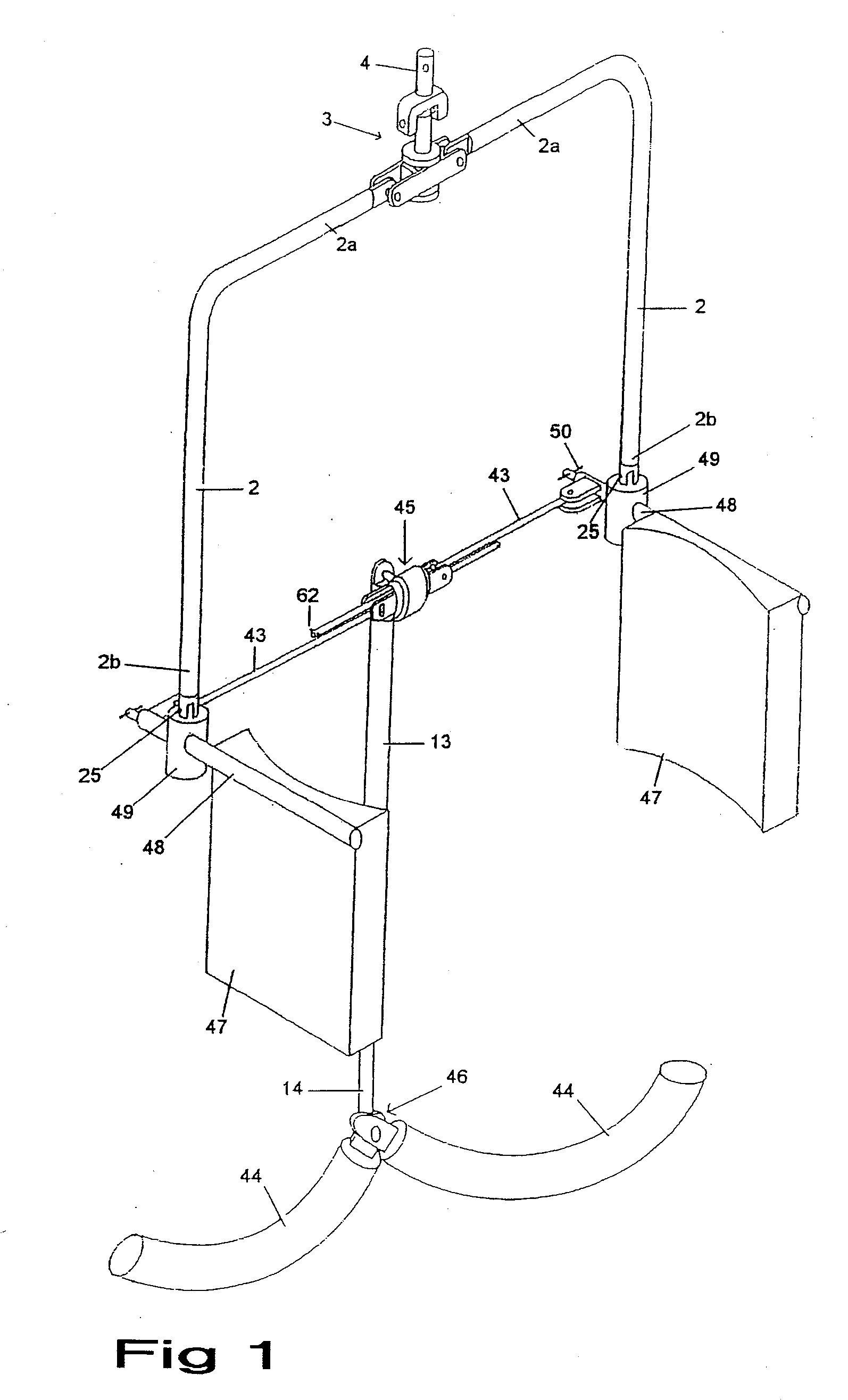
[0021] As depicted in FIG. 1, the patient lifting device 1 is constructed from a range of steel tube and rod material. The device has two side limbs 2 which are both connected at their upper ends 2a by pivots to a linkage 3 and this component carries a fastener 4 by which the device may be coupled to a lifting boom or connection piece (not shown) of a patient hoist unit.

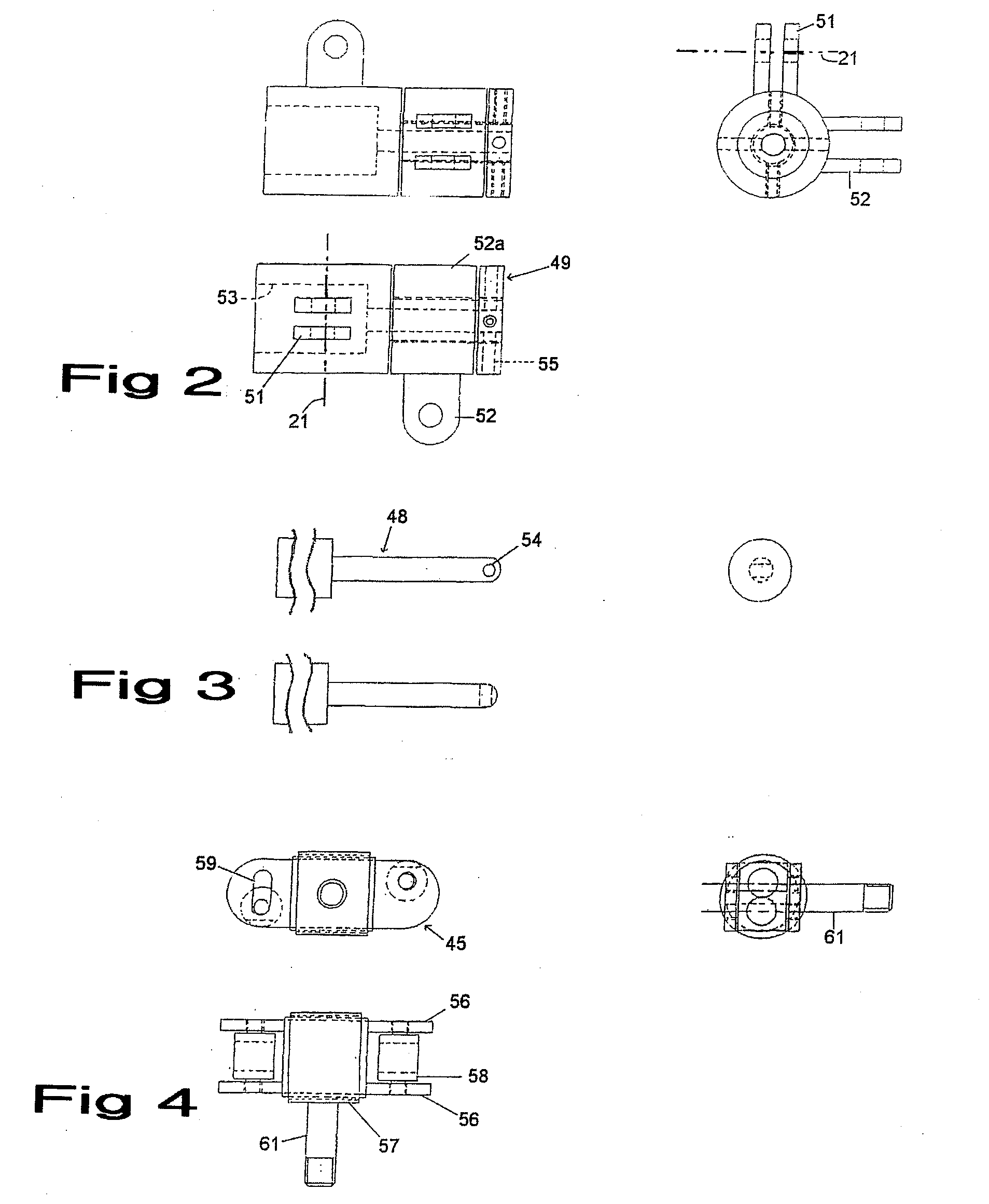
[0022] The side limbs 2 extend downwards from the linkage 3 in the shape of an inverted letter U and the lower ends 2b of the side limbs 2 are connected to side support assemblies 49 as described in greater detail below. Passing centrally through each side support assembly 49 is a support bar 48 which forwardly of the associated side support assembly mounts one end of a link bar assembly 43,45.

[0023] The link bar assembly 43,45 is formed from two mutually parallel rods 43 which are coupled together by a tee-piece in the form of a connector assembly 45. The rods 43 are thus retained parallel to one another by the co...


PUM


Abstract

A patient lifting device is provided. The patient lifting device includes two side limbs connected to a suspension mounting for suspending the device from a hoist. Each side limb includes a support bar including patient support elements. The patient support elements include a pair of side pads for engaging beneath the armpits of a patient and against sides of the patient's ribcage, and a patient upper leg or posterior support means. The two support bars connect together with an assembly from which the patient upper leg or posterior support means depends. Each support bar is pivotally mounted about a pivotal axis defining a balance axis about which the moments imparted by the weight of the patient's upper body through the side pads and by the weight of the patient's lower body through the upper leg or posterior support means can react against one another in an equal and opposite fashion.

Description

CROSS-REFERENCE TO RELATED PATENT APPLICATIONS [0001] This patent application is a continuation of PCT / GB2004 / 002529 filed Jun. 12, 2004, designating the United States, the teachings and disclosure of which are hereby incorporated in their entireties by reference thereto.FIELD OF THE INVENTION [0002] This invention relates to a patient lifting device. It relates particularly to a device which is suitable for lifting and moving an individual, for example, a person whose ability to move themselves is temporarily or permanently restricted. BACKGROUND OF THE INVENTION [0003] Many patients in a hospital or home who are physically disabled find themselves needing to be moved frequently from a lying position to a sitting or standing position. Where the patient is unable to help themselves, the movement of the patient has to be carried out by the nursing staff or carers who have to manually lift and move the patient. The heavy work involved generally means that two nurses or carers are need...

Claims


Application Information

Patent Timeline
03 May 2007
Publication
US20070094791A1
IPC
A61G7/14; A61G7/05; A61G7/10
CPC
A61G7/1015; A61G7/1053; A61G7/1074; A61G7/108; A61G7/1086; A61G7/1096; A61G2200/16; A61G2200/32
Inventors
WALKER, SIMON CHRISTOPHER DORNTON