Reference voltage generator

Inactive Publication Date: 2007-05-10
NEC ELECTRONICS CORP
View PDF7 Cites 3 Cited by
  • Summary
  • Abstract
  • Description
  • Claims
  • Application Information

AI Technical Summary

Benefits of technology

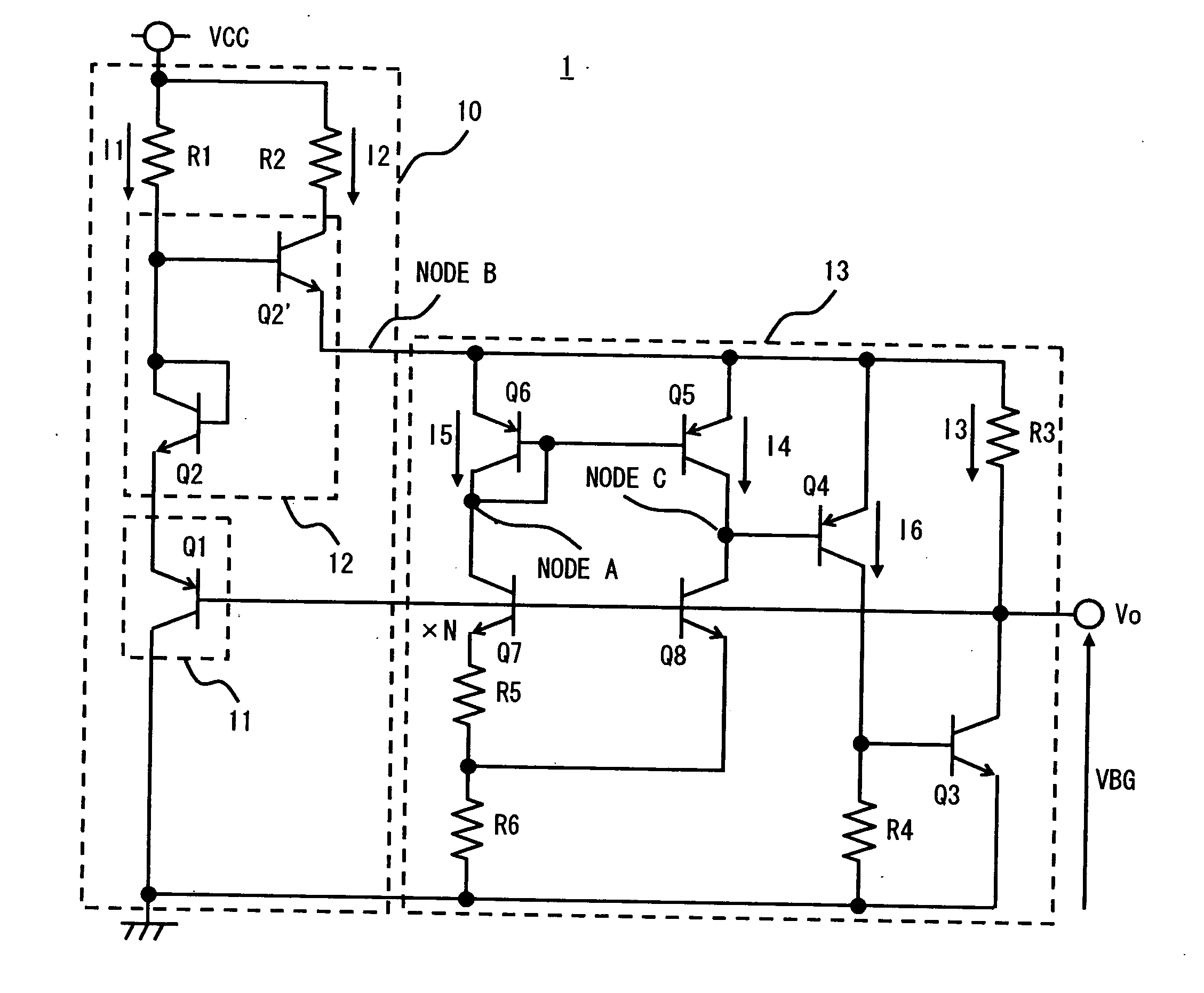
[0016] According to the reference voltage generator of the present invention, even if the third power supply (for example, power supply voltage) is changed, the voltage clamp circuit generates a first power supply (for example, a voltage of a node B) based on an output voltage that less varies than the power supply voltage, and drives the band-gap circuit using the voltage of the node B. That is, the band-gap circuit is driven based on the voltage of the node B not directly influenced by the change in power supply voltage, whereby the band-gap circuit can generate an output voltage independently of the change in power supply voltage. Hence, according to the reference voltage generator of the present invention, an output voltage that is little influenced by a change in power supply voltage can be generated.

Problems solved by technology

The reference voltage generator of the Related Art 1 has a problem in that the output voltage change relative to the power supply voltage change increases.
Thus, the Related Art 2 has a problem in terms of a performance for realizing a low-voltage operation or low power consumption.

Method used


Image

  • Reference voltage generator
  • Reference voltage generator
  • Reference voltage generator

Examples


first embodiment

[0026] Hereinafter, embodiments of the present invention are described with reference to the accompanying drawings. FIG. 1 is a circuit diagram of a reference voltage generator 1 according to a first embodiment of the present invention. The reference voltage generator 1 includes a voltage clamp circuit 10 and a band-gap circuit 13. The reference voltage generator 1 drives the band-gap circuit 13 using a voltage generated by the voltage clamp circuit 10 based on an output voltage of the band-gap circuit 13 as a power supply. Incidentally, in the following description, a control terminal, a first terminal, and a second terminal of a transistor are referred to as a base, an emitter, and a collector.

[0027] The voltage clamp circuit 10 includes a voltage setting circuit 11, a voltage buffer 12, a current setting element (for example, a resistor R1), and a resistor R2. The voltage clamp circuit 10 operates based on a second power supply (for example, a ground voltage) and a third power s...

second embodiment

[0052]FIG. 3 shows a reference voltage generator 2 according to a second embodiment of the present invention. The reference voltage generator 2 of the second embodiment includes a voltage clamp circuit 20 where a current source I1 is provided in place of the resistor R1 of the voltage clamp circuit 10 which sets the operational current I1 of the reference voltage generator 1 of the first embodiment.

[0053] An output resistance of the current source I1 is very high, so even if the power supply voltage VCC varies, an output current value is little changed. Therefore, in the reference voltage generator 1 of the first embodiment, the current I1 is changed due to the change in power supply voltage VCC. In contrast thereto, in the reference voltage generator 2 of the second embodiment, even if the power supply voltage VCC varies, a value of the current I1 is little changed.

[0054] That is, the voltage VB generated in the voltage clamp circuit 20 of the second embodiment is more stabilized...


PUM


Abstract

A reference voltage generator according to an embodiment of the present invention includes: a voltage setting circuit generating a first voltage having a predetermined voltage difference from an output voltage; a voltage buffer receiving the first voltage and outputting a first power supply substantially equal to the first voltage; a voltage clamp circuit operating based on a second power supply and a third power supply; and a band-gap circuit generating the output voltage, the band-gap circuit operating based on the second power supply and the first power supply output from the voltage clamp circuit.

Description

BACKGROUND OF THE INVENTION [0001] 1. Field of the Invention [0002] The present invention relates to a reference voltage generator, and more particularly to a reference voltage generator generating a reference voltage using a clamp voltage generated with a voltage clamp circuit as a power supply. [0003] 2. Description of Related Art [0004] Along with a recent tendency toward reduction in power supply voltage and power consumption of a semiconductor integrated circuit, an influence of a power supply voltage change or temperature change on circuit operations of the semiconductor integrated circuit becomes large. Thus, a high stability against such change has been required of the circuit. As an example of the semiconductor integrated circuit, there is a reference voltage generator. The reference voltage generator generates a reference voltage used for driving the other circuits, and needs to have a higher stability than that of the other circuits. [0005] An example of the reference vol...

Claims


Application Information

Patent Timeline
IPC IPC(8): G05F1/10
CPCG05F3/30
InventorKUWANO, TAKESHI
OwnerNEC ELECTRONICS CORP