Construction machine

a construction machine and heat exchanger technology, applied in the direction of machines/engines, mechanical equipment, transportation and packaging, etc., can solve the problems of excessive work, difficult to place and clean, and it is almost difficult to put a hand into the gap to perform maintenance, so as to improve cooling efficiency and reduce noise from the bonnet. , the effect of improving the cooling efficiency

Inactive Publication Date: 2010-11-09
YANMAR CO LTD
View PDF64 Cites 38 Cited by
  • Summary
  • Abstract
  • Description
  • Claims
  • Application Information

AI Technical Summary

Benefits of technology

[0016]The construction machine according to the present invention is adapted to contain in a bonnet an engine, a cooling fan attached to the engine, and a heat exchanger arranged so as to face to the cooling fan, wherein a shroud is provided so as to surround a space between the cooling fan and the heat exchanger in the bonnet, and a maintenance hole for putting a hand into the space therethrough is provided through an upper face of the shroud, so that it becomes possible to insert a hand into the space between the cooling fan and the heat exchanger through the maintenance hole of the shroud, and remove dirt, dust, and the like attached to a core part of the heat exchanger, which have never been able to be removed even by blowing compressed water, air, or the like toward the heat exchanger, and therefore cleaning work can be performed throughout. Also, the large space is formed between the engine and the heat exchanger, so that influence of radiation heat from the engine becomes smaller, and therefore cooling efficiency is improved.
[0017]The construction machine according to the present invention is adapted such that a splitter for changing a blowing direction of cooling wind from the cooling fan is removably arranged in the space between the cooling fan and the heat exchanger, the space being surrounded by the shroud, so that the splitter can change the blowing direction of the cooling wind from the cooling fan to feed the cooling wind throughout the heat exchanger such as a radiator or oil cooler, and therefore the cooling efficiency can be improved. Also, noise leaking outside from the bonnet can be reduced. Further, maintenance, or the like, of the cooling fan or heat exchanger can be easily performed if the splitter is removed.
[0018]The construction machine according to the present invention is adapted such that a plate-like attaching plate is removably attached to the upper face of the shroud so as to cover the maintenance hole, and the splitter is vertically installed downward from the attaching plate through the maintenance hole, so that the splitter can be attached or removed with a simple configuration. Also, the bonnet can be opened to remove the splitter from above, and therefore it becomes possible to insert a hand from the maintenance hole to perform maintenance of the cooling fan or heat exchanger.
[0019]The construction machine according to the present invention is adapted such that a part covering a region from the cooling fan to the heat exchanger in the bonnet from above and sides includes a separate cover; an opening part having a guard is provided through a portion of the cover, the portion facing to the heat exchanger; and the cover is openable and closable, so that it becomes possible to insert a hand into the space between the cooling fan and the heat exchanger from above, rear, or side to perform the cleaning work if the cover is simply opened, and therefore the cleaning work of an outside of the heat exchanger can be easily performed from the side (outside). Also, the heat exchanger can be opened to the outside separately from a main body of the bonnet, so that it is not necessary to open the entire bonnet for the purpose of the cleaning work, and also the dust and the like are not scattered into the bonnet on the engine side at the time of cleaning work.
[0020]The construction machine according to the present invention is adapted such that the cooling fan arranged in the bonnet is of a discharge type, so that water or air can be laterally discharged to the heat exchanger from the outside being in a direction opposite to a discharging direction, and therefore the dust and the like attached to the heat exchanger can be blown out or washed out to be thereby easily removed.
[0021]The construction machine according to the present invention is adapted such that a plurality of the heat exchangers are arranged in a same plane, so that the plurality of heat exchangers are arranged in a state where the space between the cooling fan and the heat exchanger is kept large enough to put a hand inside, and therefore a hand can be inserted into the space to clean any of the heat exchangers.

Problems solved by technology

The clogging of the radiator core or filter occurs with long-term use, and in particular, if work such as dismantlement of a building is performed with use of a construction machine such as a power shovel equipped with the radiator, fibriform dust such as glass fibers used as a heat insulating material is deposited on the heat exchanger, which is likely to cause overheating, so that it is necessary to clean it every time the overheating occurs.
However, the technique described in Patent document 1 is not preferable because if a mesh of the net is made fine enough to capture the glass fibers, the net is clogged in a short time, and therefore the cleaning work should be more frequently performed.
Also, in the technique described in Patent document 2, because the upper and lower tanks are respectively connected with hoses, a range within which the heat exchanger can be moved is limited, which not only makes it difficult to place and clean the heat exchanger at a desirable position, but also twists or removes the hoses, thus creating excessive work.
On the other hand, in recent years, a gap between the cooling fan and the heat exchanger is allocated so as to be considerably small so that an engine room can compactly contain the engine, heat exchanger, hydraulic instruments, and the like to be downsized, however, this is in a state where it is almost difficult to put a hand into the gap to perform maintenance, and therefore decomposition is the only way to perform the maintenance.

Method used


Image

  • Construction machine
  • Construction machine
  • Construction machine

Examples


Embodiment Construction

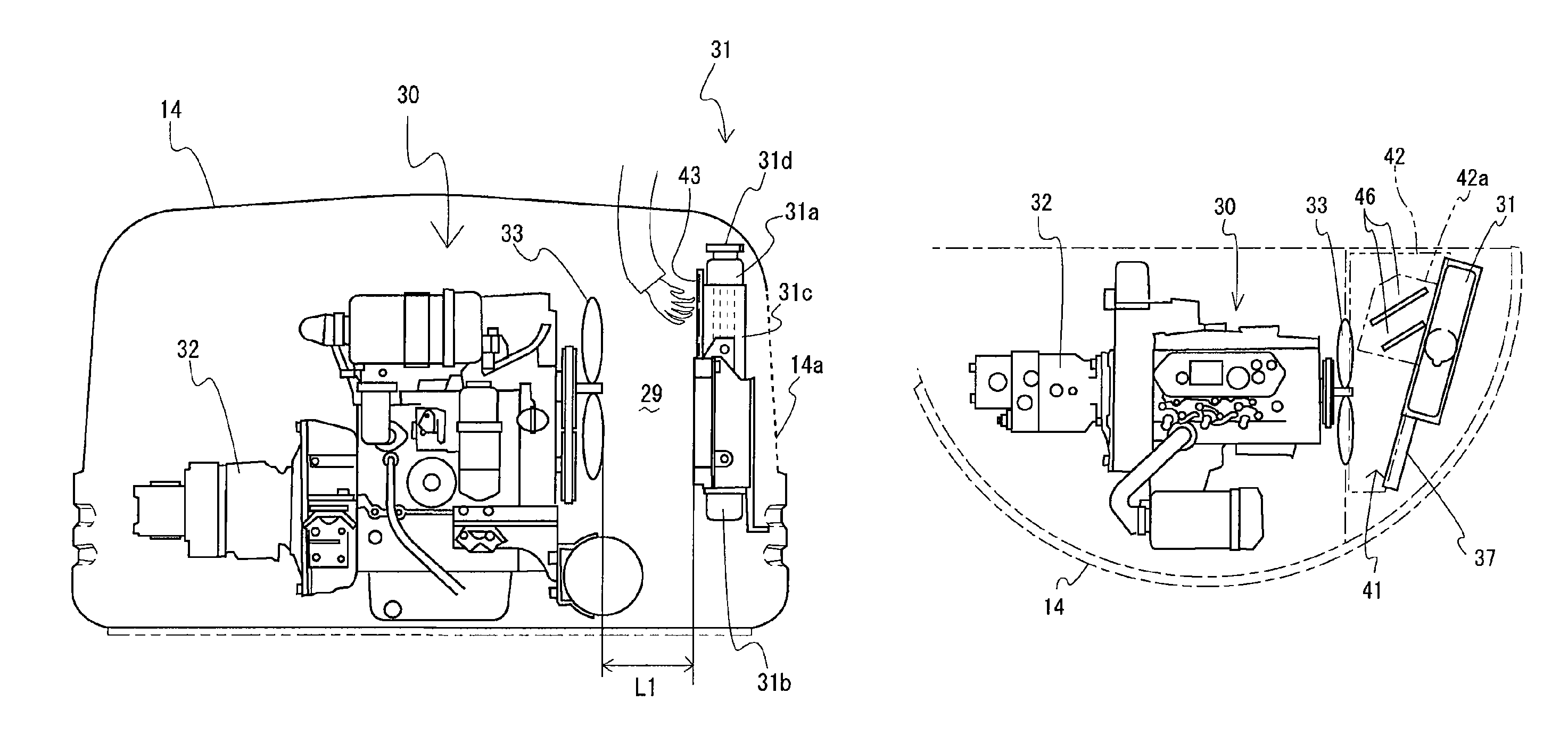
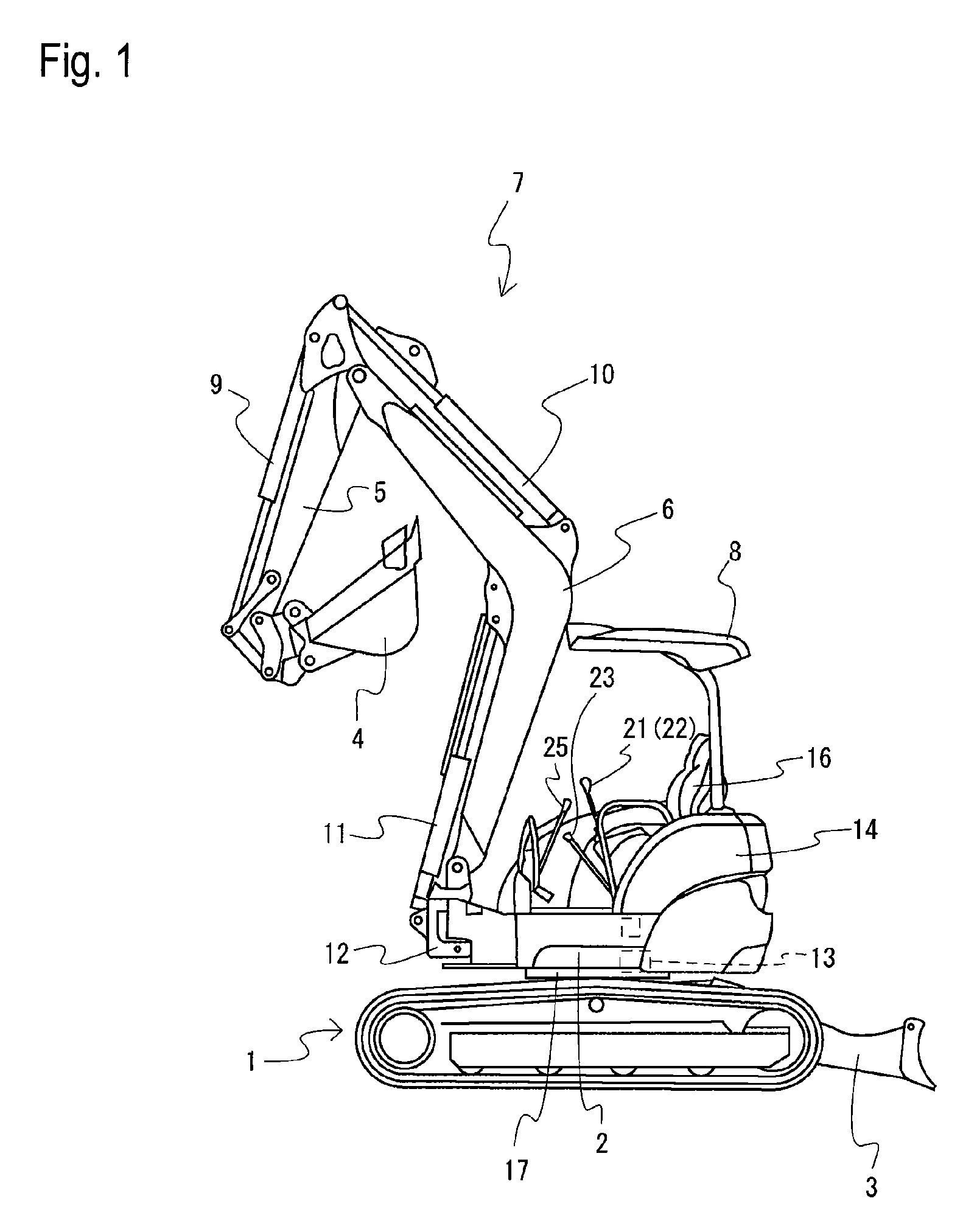
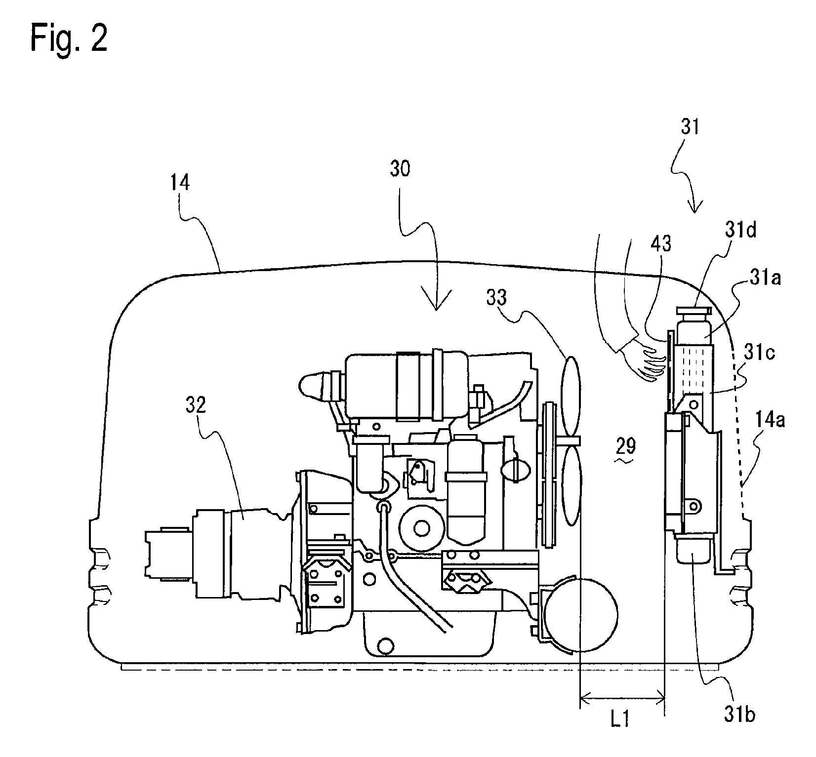
[0043]First, as an excavation working vehicle that is one of construction machines of the present invention each equipped with a heat exchanger, a power shovel is described as an embodiment. In FIG. 1, the power shovel is attached with a working machine 7 in a front part of the main machine; the main machine supports a rotation frame 2 in the center of an upper face of a crawler type traveling device 1 via a rotation table bearing 17 such that the rotation frame 2 can rotate right and left; and a hydraulic motor 13 for the rotation is arranged on the rotation frame 2. On one of a front or rear side of the crawler type traveling machine 1, a blade 3 is allocated so as to be able to rotationally move up and down. Also, a driving operation part is configured such that a bonnet 14 covering an engine and the like is allocated on the rotation frame 2; a driver's seat 16 is arranged on or in front of the bonnet 14; hydraulic operation levers 21 and 22, lock lever 23, and the like are arran...


PUM


Abstract

An object is to provide a construction machine containing an engine (30) and a heat exchanger (31) in a bonnet (14), adapted for easy cleaning of a side of the heat exchanger (31) toward a cooling fan.A space (29) into which a hand can be put is provided between a cooling fan 33 attached to the engine (30) and the heat exchanger (31) arranged so as to face to the cooling fan (33). A part covering a region from the cooling fan (33) to the heat exchanger (31) in the bonnet (14) from above and sides includes a separate cover (34). An opening part having a guard (36) is provided through a portion of the cover (34), the portion facing to the heat exchanger (31). The cover (34) is configured to be openable and closable. The cooling fan (33) is adapted to be of a discharge type. A plurality of the heat exchangers are arranged in a same plane.

Description

TECHNICAL FIELD[0001]The present invention relates to a heat exchanger provided for an engine of a construction machine, and more particularly to a technique for facilitating cleaning of an air inlet part of the heat exchanger.BACKGROUND ART[0002]A radiator is arranged for an engine as a heat exchanger to cool a cylinder block and the like. The radiator is adapted such that a radiator core is arranged between an upper tank and a lower tank; the lower tank is connected to a water pump via a hose or the like to convey cooling water, which has been cooled by heat exchanging at the radiator core, to a water jacket of the engine; and the cooling water, which has been warmed by cooling the engine, is returned to the upper tank via a hose. The radiator core is improved in terms of radiation performance by arranging a large number of fine tubes between the upper tank and the lower tank in a longitudinal direction, and arranging in parallel a large number of fins orthogonally to the tubes or...

Claims


Application Information

Patent Timeline
Patent Type & Authority Patents(United States)
IPC IPC(8): B60K11/00
CPCB60K11/02B60K11/04B60K11/085B62D25/10E02F9/0833E02F9/0891F01P11/10F01P11/12F01P5/02F01P2001/005Y02T10/88E02F9/00
Inventor KONDOU, MASAMISEINO, HIDEKI
Owner YANMAR CO LTD
Why Eureka
Try Eureka