Multi-Layer Ceramic Capacitor and Method of Producing the Same

Active Publication Date: 2017-06-15
TAIYO YUDEN KK
View PDF6 Cites 29 Cited by
  • Summary
  • Abstract
  • Description
  • Claims
  • Application Information

AI Technical Summary

Benefits of technology

[0023]It is possible to provide a multi-layer ceramic capacitor and a method of producing the mul

Problems solved by technology

This may lead to occurrence of cracks and peel-off between the multi-layer chip and the side margins and al

Method used


Image

  • Multi-Layer Ceramic Capacitor and Method of Producing the Same
  • Multi-Layer Ceramic Capacitor and Method of Producing the Same
  • Multi-Layer Ceramic Capacitor and Method of Producing the Same

Examples


Embodiment Construction

[0035]Hereinafter, an embodiment of the present invention will be described with reference to the drawings.

[0036]In the figures, an X axis, a Y axis, and a Z axis orthogonal to one another are shown as appropriate. The X axis, the Y axis, and the Z axis are common in all figures.

1. Overall Configuration of Multi-layer Ceramic Capacitor 10

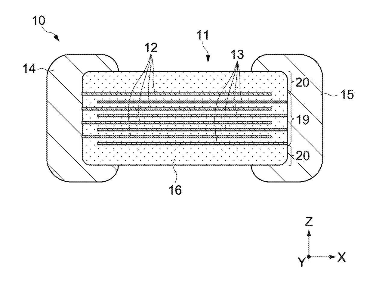
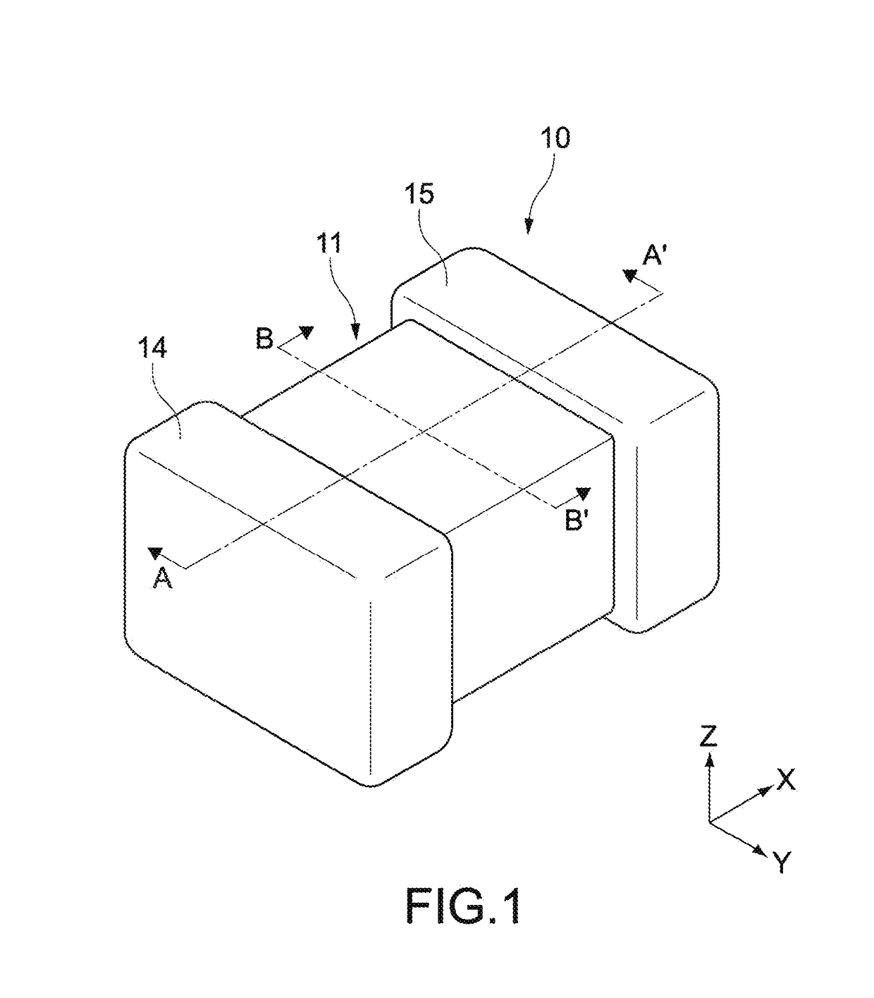
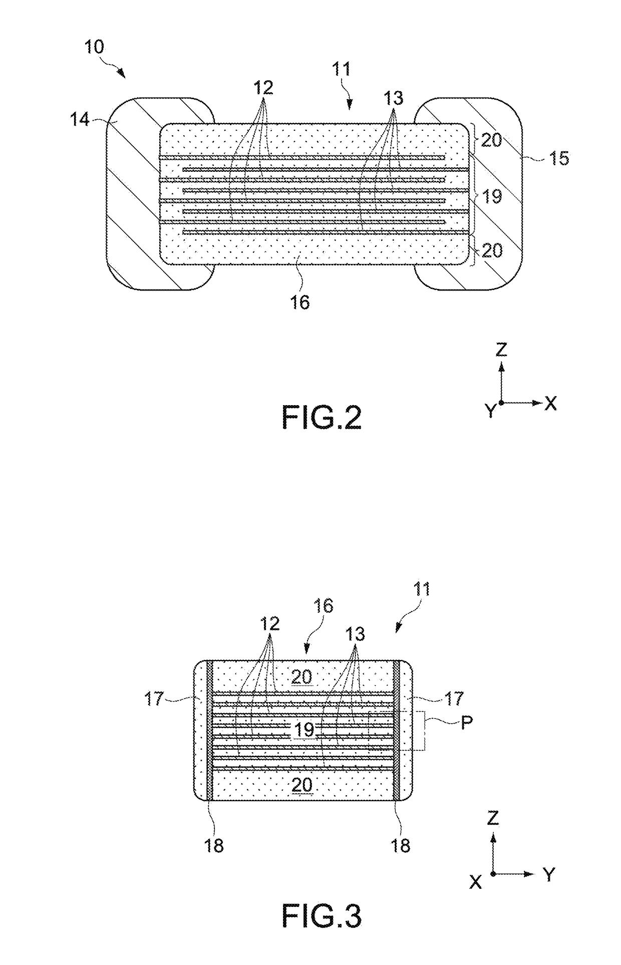
[0037]FIGS. 1 to 3 each show a multi-layer ceramic capacitor 10 according to an embodiment of the present invention. FIG. 1 is a perspective view of the multi-layer ceramic capacitor 10. FIG. 2 is a cross-sectional view of the multi-layer ceramic capacitor 10 taken along the A-A′ line in FIG. 1. FIG. 3 is a cross-sectional view of the multi-layer ceramic capacitor 10 taken along the B-B′ line in FIG. 1.

[0038]The multi-layer ceramic capacitor 10 includes a body 11, a first external electrode 14, and a second external electrode 15.

[0039]Typically, the body 11 has two side surfaces oriented in a Y-axis direction and two main surfaces oriented in a Z-ax...


PUM

PropertyMeasurementUnit
Thicknessaaaaaaaaaa
Thicknessaaaaaaaaaa
Contentaaaaaaaaaa

Abstract

A multi-layer ceramic capacitor includes a multi-layer unit, side margins, and bonding units. The multi-layer unit includes ceramic layers laminated in a first direction and internal electrodes disposed between the ceramic layers. The side margins cover the multi-layer unit from a second direction orthogonal to the first direction. The bonding units are each disposed between the multi-layer unit and each of the side margins and have higher silicon content than the ceramic layers and the side margins.

Description

CROSS REFERENCE TO RELATED APPLICATIONS[0001]This application claims priority under 35 U.S.C. §119 to Japanese Patent Application No. 2015-243881, filed Dec. 15, 2015, which is hereby incorporated by reference in its entirety.BACKGROUND[0002]The present invention relates to a multi-layer ceramic capacitor including side margins provided in a subsequent step, and to a method of producing the multi-layer ceramic capacitor.[0003]Along with miniaturization and achievement of high performance of electronic devices, there have recently been increasingly strong demands for miniaturization and increase in capacity with respect to multi-layer ceramic capacitors used in the electronic devices. In order to meet those demands, it is effective to enlarge internal electrodes of the multi-layer ceramic capacitor. In order to enlarge the internal electrodes, it is necessary to thin side margins for ensuring insulation properties of the periphery of the internal electrodes.[0004]Meanwhile, in a gene...

Claims


Application Information

Patent Timeline
IPC IPC(8): H01G4/30H01G4/005H01G4/12
CPCH01G4/30H01G4/005H01G4/1227H01G4/12H01G4/224H01G4/232H01G4/2325H01G4/012
Inventor KATO, YOICHIMIZUNO, KOTAROKONISHI, YUKIHIRO
Owner TAIYO YUDEN KK
Why Eureka
Try Eureka