Eureka AIR delivers breakthrough ideas for toughest innovation challenges, trusted by R&D personnel around the world.

Angled medical connector with height compensator

Active Publication Date: 2007-05-10
TRI STATE HOSPITAL SUPPLY
View PDF16 Cites 4 Cited by
  • Summary
  • Abstract
  • Description
  • Claims
  • Application Information

AI Technical Summary

Benefits of technology

[0006] The present invention provides an angled medical connector for connecting medical tubing to a catheter. The connector includes a connector body and a height compensating foot mounted thereon. The height compensating foot compensates for the larger diameter of the catheter connector and prevents rocking of the connector when connected to a catheter inserted in a patient.
[0007] Further, the angled medical connector of the present invention overcomes deficiencies of conventional fittings and tubing. When an IV catheter is inserted on the back of the hand, conventional fittings and tubing connected to the catheter hang over the knuckles of the hand. It is common that the fittings / tubing may overhang between a half inch and one and a half inches. This configuration has a high risk of catheter dislodgement, blood vessel damage, dressing rip up, etc. due to snagging or pulling on the overhanging fittings / tubing. The present angled connector reduces the risk of these occurrences by routing the fittings and tubing away from the knuckles on a hand, preventing knuckle overhang. The present invention also eliminates the need to use rigidizing arm boards and the like.
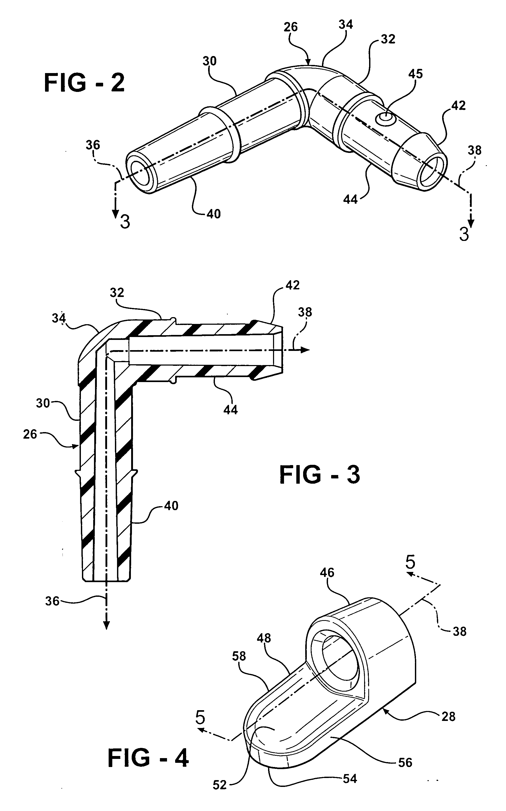
[0008] In an exemplary embodiment of the present invention a medical connector includes a connector body and a height compensating foot. The connector body has an elongated hollow catheter leg having a first end portion adapted to detachably connect to a catheter. A first axis extends centrally through the hollow portion of the catheter leg. The connector body also has an elongated hollow medical tubing leg having a second end portion adapted to connect to medical tubing. A second axis extends centrally through the hollow portion of the medical tubing leg. The connector body further includes an angular bend intermediate the catheter leg and medical tubing leg wherein the first and second axes intersect. The height compensating foot is attached to the medical tubing leg and extends outwardly therefrom at an angle to prevent rocking about the first and second axis when connected to the catheter inserted in a patient.

Problems solved by technology

This configuration has a high risk of catheter dislodgement, blood vessel damage, dressing rip up, etc. due to snagging or pulling on the overhanging fittings / tubing.

Method used


Image

  • Angled medical connector with height compensator
  • Angled medical connector with height compensator
  • Angled medical connector with height compensator

Examples


Embodiment Construction

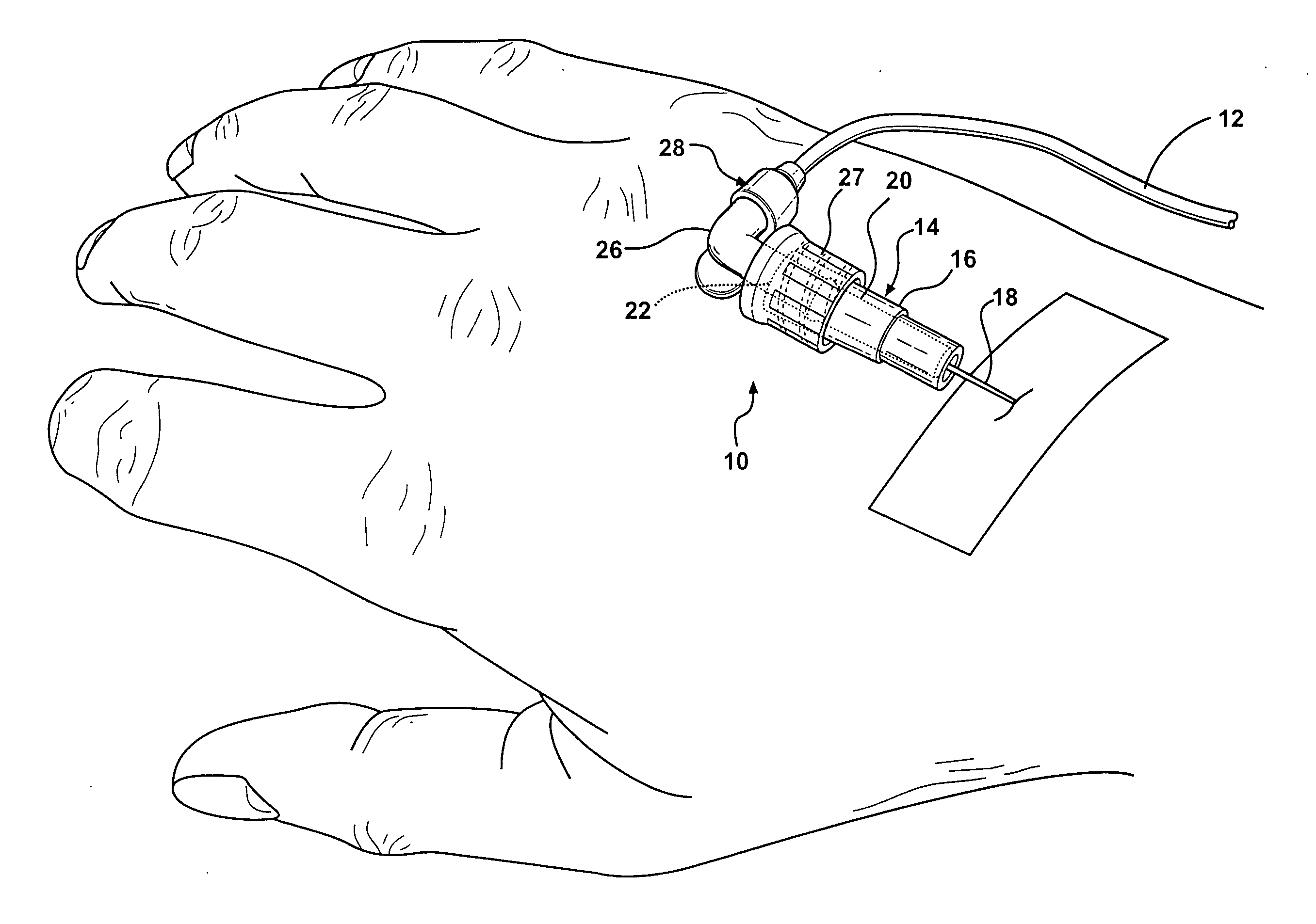
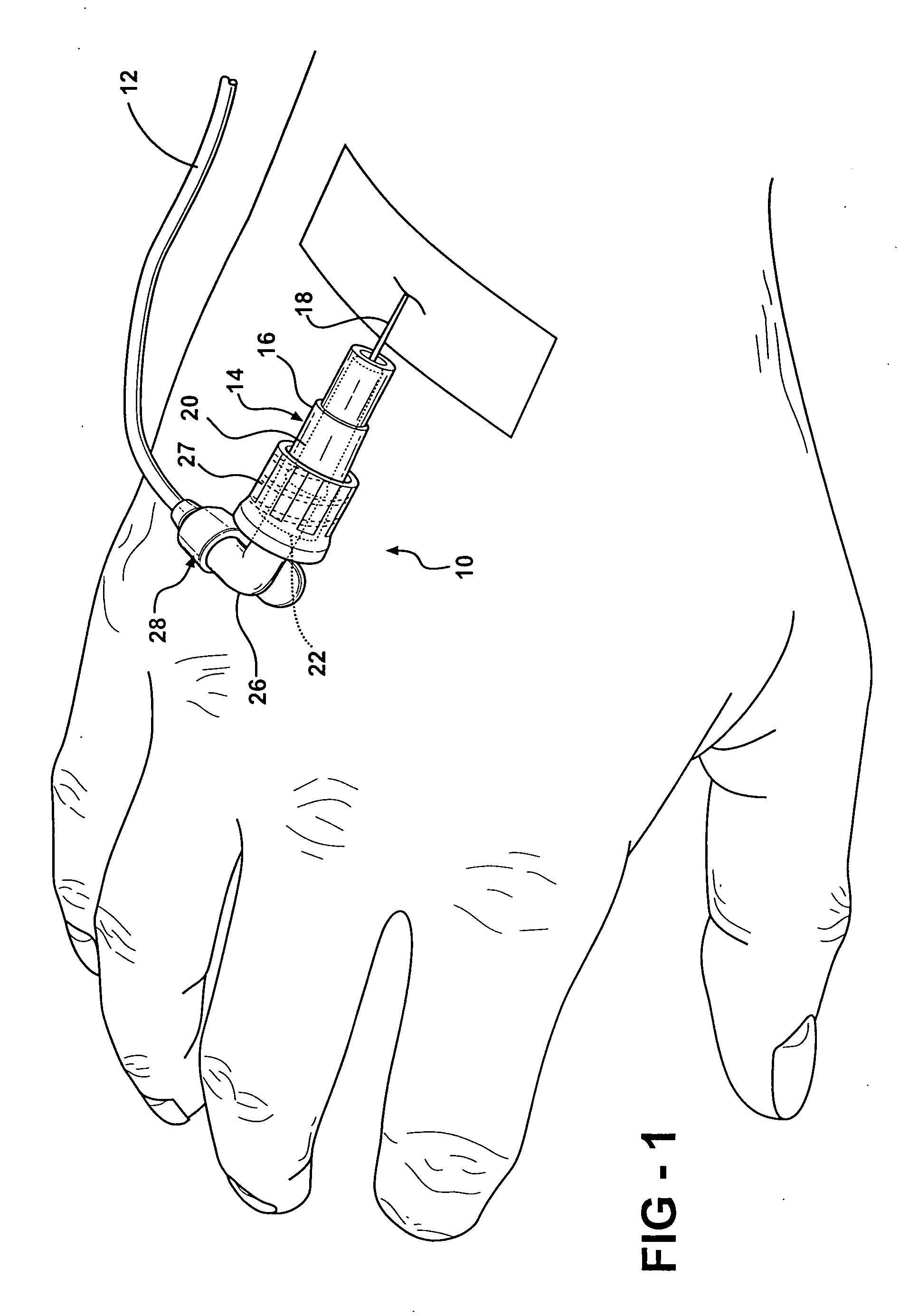
[0024] Referring now to FIG. 1, numeral 10 generally indicates an exemplary embodiment of an angled medical connector in accordance with the present invention. Medical connector 10 is shown connecting IV tubing 12 to catheter 14, which is inserted into a patient.

[0025] The IV tubing 12 is typically connected to a container of IV fluid, which is generally positioned to allow the IV fluid to be fed through the tubing 12, connector 10 and catheter 14 into the patient. Although IV tubing is illustrated herein, one skilled in the art will recognize that the connector 10 may be utilized with other types of medical tubing, such as surgical drainage tubes, feeding tubes, or the like.

[0026] The catheter 14 is hollow and includes a hub 16 and a sheath 18 fluidly connected to the front end of the hub 16. The sheath 18 of the catheter 14 is typically inserted as is known into a vein of the patient and used to administer IV fluids or the like. The interior surface 20 of the hub 16 has a conica...


PUM


Abstract

A medical connector for connecting medical tubing to a catheter includes a connector body and a height compensating foot. The connector body has a catheter leg adapted to connect to the catheter, a medical tubing leg adapted to connect to the medical tubing, and an angular bend intermediate the legs. The height compensating foot is attached to the catheter leg and extends outwardly therefrom at an angle to prevent the connector from rocking and tubing from overhanging a patient's knuckles when connected to the catheter inserted in a patient.

Description

TECHNICAL FIELD [0001] This invention relates to medical connectors and more specifically to an angled medical connector that compensates for the difference in height between a catheter lumen and an associated connector disposed on a patient. BACKGROUND OF THE INVENTION [0002] In the medical and surgical fields, intravenous (IV) fluids are generally administered to a patient through a catheter inserted into a vein of the patient. The catheter is typically coupled to an IV connector, which is connected by IV tubing to a container of IV fluid. [0003] Generally the catheter includes an insertion end and a connecting end configured as a female fitting having a diameter substantially larger than the catheter itself. A cooperating connector has a male fitting portion adapted to mate with the female fitting. The female and male fittings are commonly configured as luer lock type fittings. As luer fittings, the male portion of the IV connector has a precise tapered outer surface, and the cat...

Claims


Application Information

Patent Timeline
IPC IPC(8): A61M25/16
CPCA61M5/158A61M39/10A61M2005/1416
Inventor GILLIS, GARY A.
Owner TRI STATE HOSPITAL SUPPLY
Why Eureka
Eureka Blog
Learn More