Vertical mount mass flow sensor

a sensor and mass flow technology, applied in liquid/fluent solid measurement, process and machine control, instruments, etc., can solve the problem of the span or dynamic range of the mass flow meter of the mass flow controller, and the shift of the calibration value, so as to prevent thermal siphoning, prevent thermal siphoning, and prevent thermal siphoning.

Active Publication Date: 2007-05-24
MKS INSTR INC
View PDF5 Cites 19 Cited by
  • Summary
  • Abstract
  • Description
  • Claims
  • Application Information

AI Technical Summary

Benefits of technology

[0004] A thermal mass flow meter for measuring flow rate of a fluid includes a conduit that is configured to receive the fluid and that defines a primary flow path between an inlet and an outlet of the conduit. The conduit is bound at least in part by a sensor receiving surface. A thermal sensing portion of a thermal sensor tube is mounted relative to the sensor receiving surface in a direction substantially perpendicular to both the primary flow path and the sensor receiving surface. When the thermal mass flow meter is mounted in a vertical direction so that fluid within the conduit flows in the vertical direction along the primary flow path, fluid within the sensor tube flows in a horizontal direction so as to substantially prevent thermal siphoning when the sensor tube is heated.
[0006] When the thermal mass flow meter is mounted in a substantially vertical direction so that fluid within the conduit flows in the vertical direction along the primary flow path, fluid within the thermal sensing portion of the sensor tube may flow in a horizontal direction so as to substantially prevent thermal siphoning when the sensor tube is heated.
[0007] A method is described for preventing thermal siphoning in a mass flow controller for controlling flow rate of a fluid. The mass flow controller includes a thermal sensor tube has a thermal sensing portion, and further includes a conduit configured to receive the fluid. The conduit defines a primary flow path between an inlet and an outlet of the conduit, and is bounded at least in part by a sensor receiving surface. The method includes mounting the thermal sensing portion of the sensor tube in a direction substantially perpendicular to both the primary flow path and the sensor receiving surface. When the mass flow controller is mounted in a vertical direction so as to cause fluid within the conduit to flow along the primary flow path in the vertical direction, fluid within the thermal sensing portion of the sensor tube may flow along a horizontal direction so as to substantially prevent thermal siphoning when the sensor tube is heated.

Problems solved by technology

In addition to causing the zero point calibration in mass flow controllers to shift, thermal siphoning may also cause a calibration shift in the span or dynamic range of the mass flow meter of the mass flow controller.

Method used


Image

  • Vertical mount mass flow sensor
  • Vertical mount mass flow sensor
  • Vertical mount mass flow sensor

Examples


Embodiment Construction

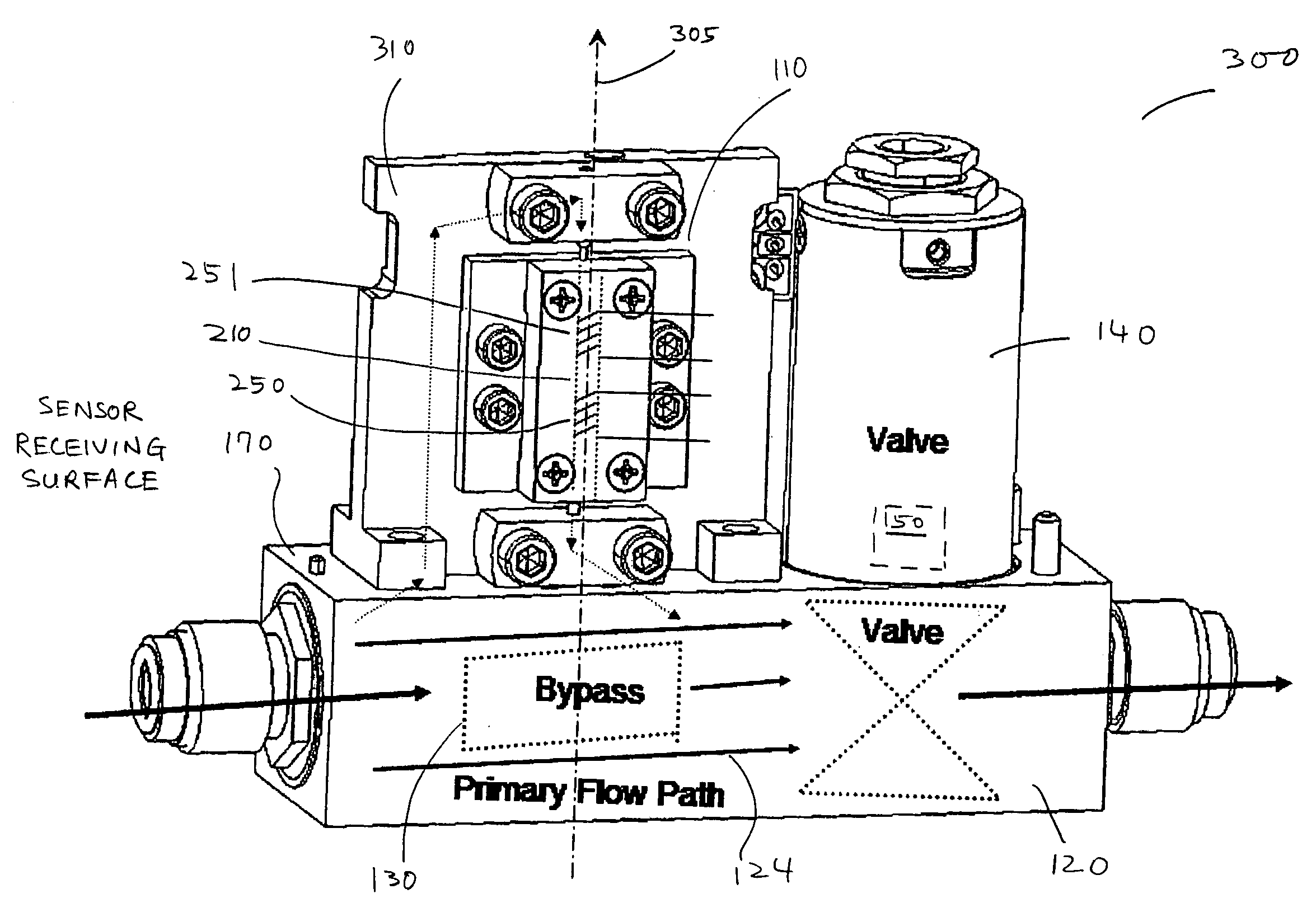
[0011] A system and method are described for substantially preventing thermal siphoning in a thermal mass flow controller when the mass flow controller is vertically mounted.

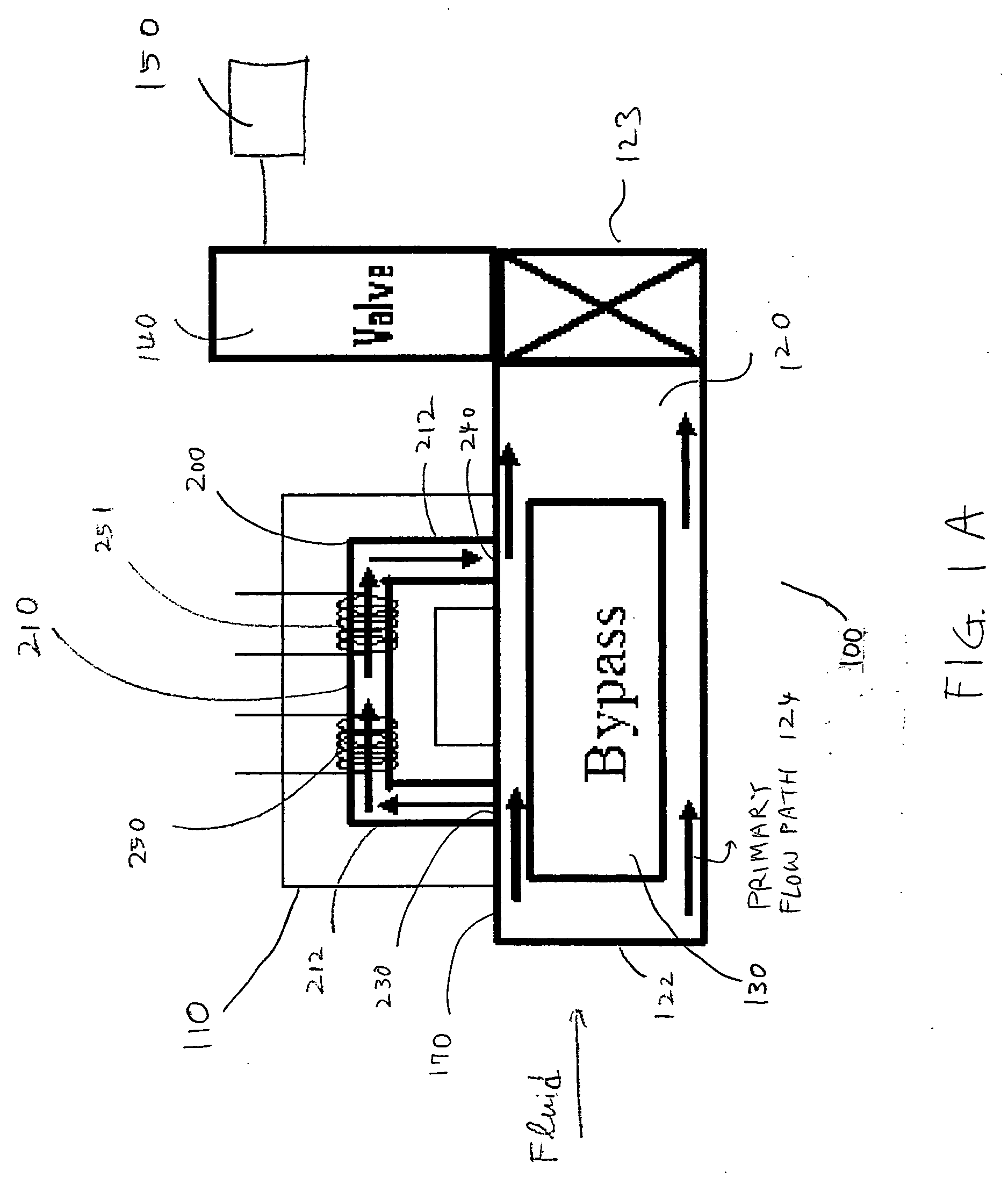
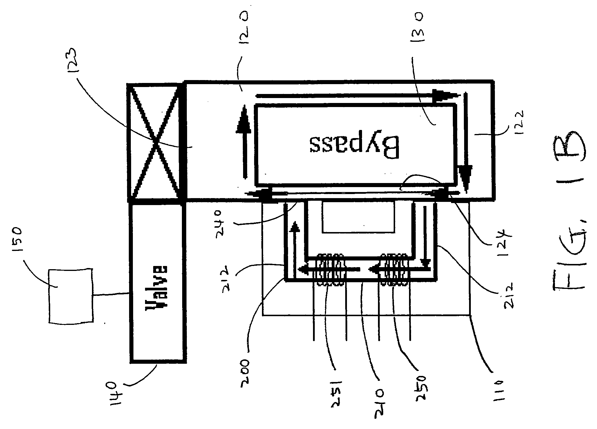
[0012] FIGS 1A and 1B schematically illustrate the operation of a typical thermal MFC that measures and controls the mass flow rate of fluids, and also illustrate thermal siphoning that may occur when the MFC is mounted vertically, as shown in FIG. 1B. FIG. 1A illustrates a horizontally mounted thermal MFC, while FIG. 1B illustrates a thermal MFC that is the same as the MFC shown in FIG. 1A, but that is mounted vertically. In overview, thermal MFCs may measure the mass flow rate of a fluid by using the thermal properties of fluids and monitoring the temperature change of the heated sensor tube as the fluid flows therethrough. A thermal MFC may typically include a thermal mass flow meter which actually measures the mass flow rate of fluids, and a control assembly (including a valve and electronic control circuit...


PUM


Abstract

A thermal mass flow meter for measuring flow rate of a fluid includes a conduit that is configured to receive the fluid and that defines a primary flow path between an inlet and an outlet of the conduit. The conduit is bound at least in part by a sensor receiving surface. A thermal sensor tube has a thermal sensing portion that is mounted relative to the sensor receiving surface in a direction substantially perpendicular to both the primary flow path and the sensor receiving surface. When the thermal mass flow meter is mounted in a vertical direction so that fluid within the conduit flows in the vertical direction along the primary flow path, fluid within the sensor tube flows in a horizontal direction so as to substantially prevent thermal siphoning when the sensor tube is heated.

Description

BACKGROUND OF THE INVENTION [0001] Thermal siphoning in a mass flow controller (MFC) may refer to a continuous circulation of gas caused by the free convection between the heated thermal flow sensor and the bypass. Thermal siphoning may result in a non-zero output signal for the flow rate that resembles zero point drift, even when the actual output flow rate is zero. In some MFC designs, thermal siphoning effects may be more likely to occur if the mass flow controller is installed vertically, and may vary in proportion with the molecular weight and pressure of the fluid whose flow rate is being controlled. [0002] In addition to causing the zero point calibration in mass flow controllers to shift, thermal siphoning may also cause a calibration shift in the span or dynamic range of the mass flow meter of the mass flow controller. [0003] A method and system are needed that can prevent or reduce thermal siphoning effects when a thermal mass flow controller is vertically mounted, and tha...

Claims


Application Information

Patent Timeline
Patent Type & Authority Applications(United States)
IPC IPC(8): G01F1/68
CPCG01F1/6847G05D7/0635G01F5/00G05D7/0629G01F1/68
Inventor DING, JUNHUAL'BASSI, MICHAELZARKAR, KAVEH H.
Owner MKS INSTR INC
Why Eureka
Try Eureka