Reversible electric pump and paint roller assembly

a technology of electric pump and paint roller, which is applied in the direction of positive displacement liquid engine, brushes, coatings, etc., can solve the problems of wasting paint and contaminating the environment, and achieve the effect of preventing wasting paint and contaminating the environment, and easy cleaning of the paint dispenser

Inactive Publication Date: 2007-06-14
DIVERSIFIED DYNAMICS
View PDF12 Cites 30 Cited by
  • Summary
  • Abstract
  • Description
  • Claims
  • Application Information

AI Technical Summary

Benefits of technology

[0013] A principal object and advantage of the present invention is that it permits an electric pump to alternately pump paint from a paint can toward the roller and from the roller back to the paint can.
[0014] Another principal object and advantage of the present invention is that it prevents wasting paint and contaminating the environment with paint dripping from the roller and hose.
[0015] Another principal object and advantage of the present invention is that it enables easy clean-up of the paint dispenser.

Problems solved by technology

However, in order to clean the apparatus after painting, it is necessary to pump any remaining paint that is in the hose and handle through the roller and then scrape the paint off into the can.
During this procedure, paint may drip from the roller onto the environment, resulting in wasting paint and contaminating the environment.

Method used


Image

  • Reversible electric pump and paint roller assembly
  • Reversible electric pump and paint roller assembly
  • Reversible electric pump and paint roller assembly

Examples


Embodiment Construction

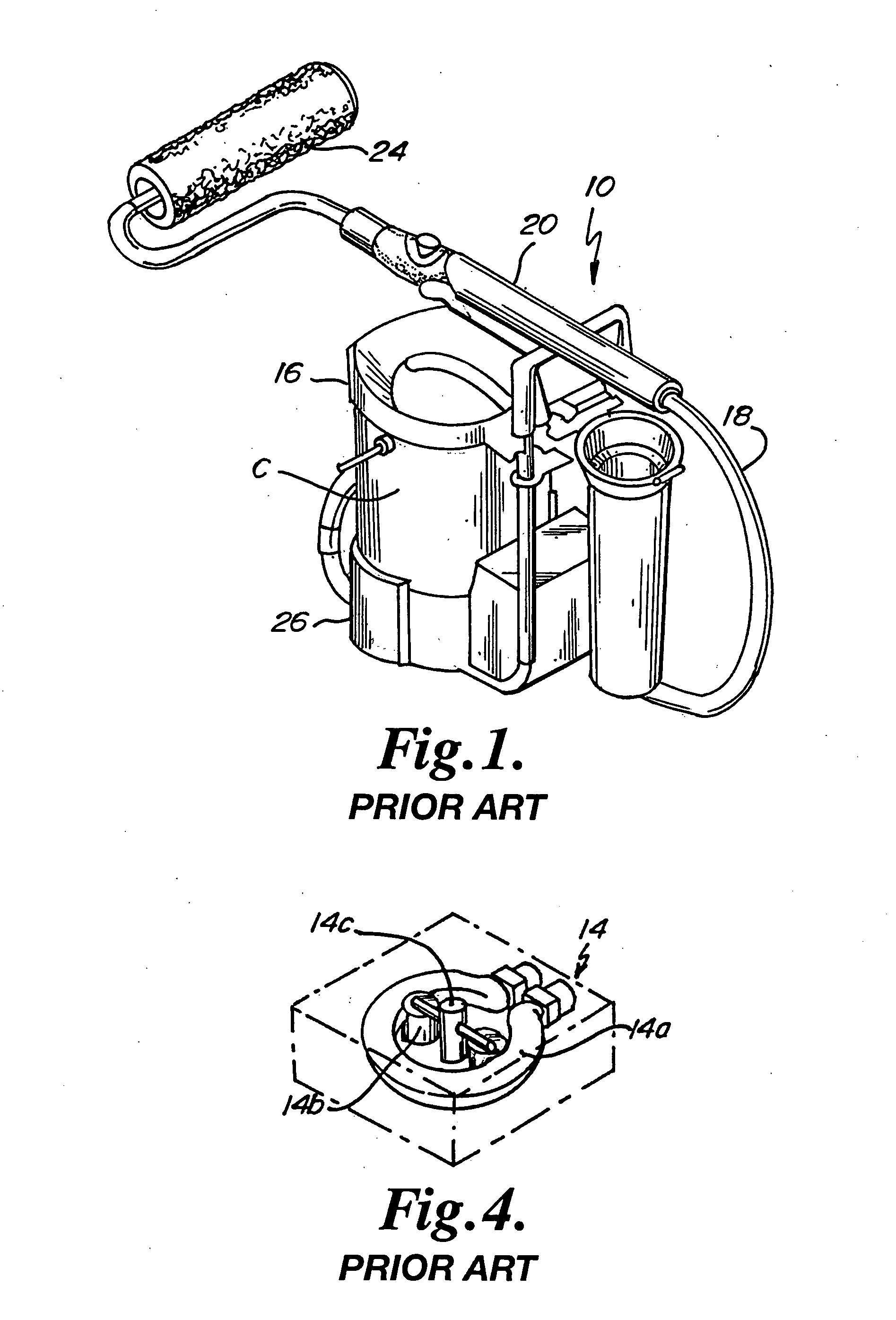
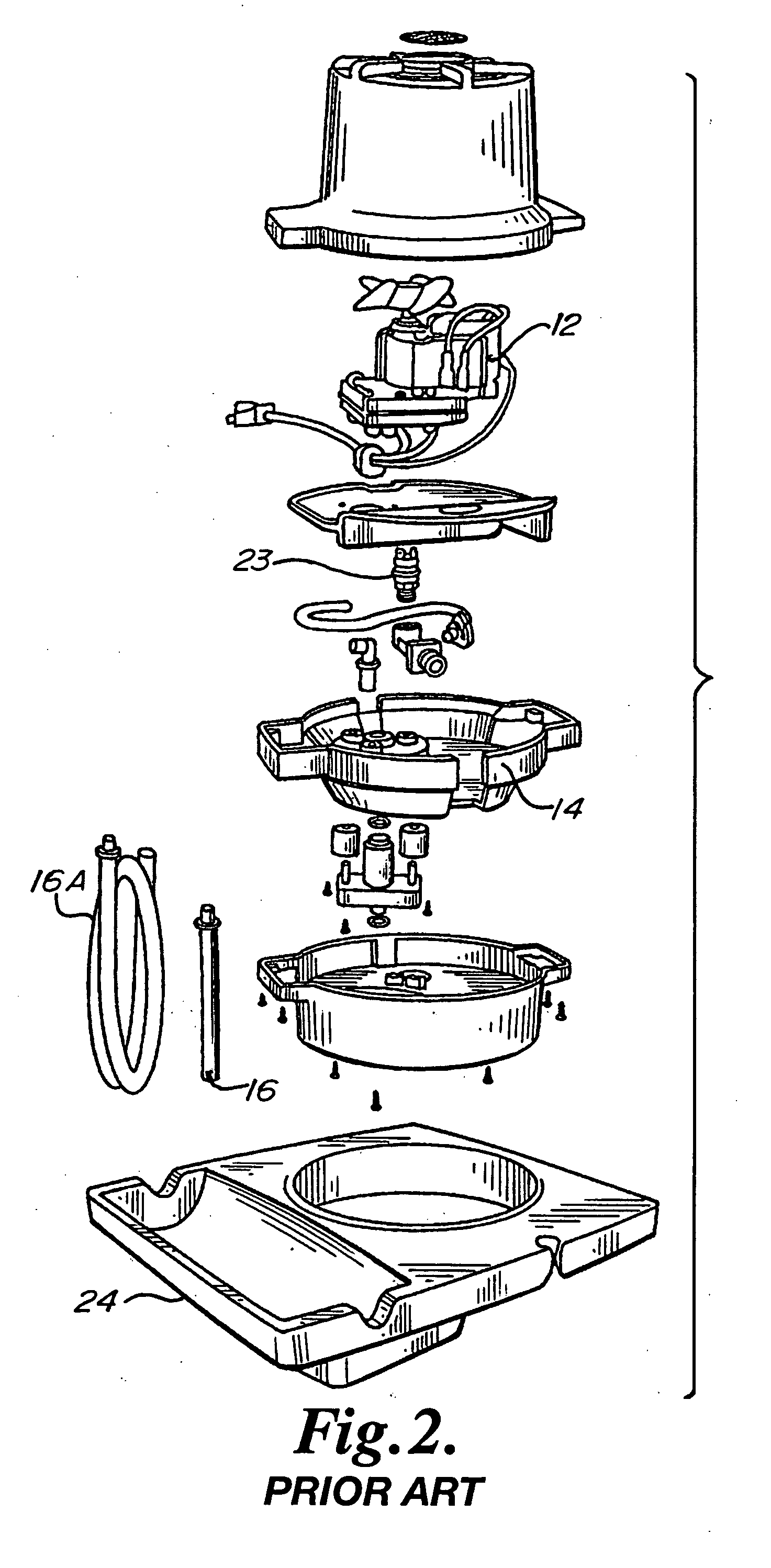
[0023] A typical dispenser of the prior art is available from HomeRight, 1661 94th Lane N.E., Minneapolis, Minn. 55449-4324, as the Electric Power-Flo Roller Painting System.

[0024] As shown in FIGS. 1-4, the dispenser 10 comprises a motor 12, a pump such as a peristaltic pump 14 driven by the motor 12, suction tube 16 connected to the peristaltic pump 14, hose 18, handle 20 connected to the hose, pressure switch 22, and roller 24.

[0025] To set up the apparatus for painting, the roller 24 is connected to the handle 20, which has an internal bore 21 through which paint flows to the roller 24. The hose 18 is suitably connected to the handle 20 and to the peristaltic pump 14. The suction tube 16 is connected to the peristaltic pump 14. The apparatus 10 is then placed onto an open one-gallon paint can C with the suction tube 16 dipping into the paint in the can. Alternatively, a longer suction tube 16A may be placed in the paint can and run to the unit 10 at a nearby location. Electric...


PUM


Abstract

A paint roller dispenser apparatus has an electric motor; a pump driven by the motor; a tube connected to the pump for receiving paint; a hose connected to the pump; a handle; a paint roller connected to the hose and to the handle; and a mechanism for reversing the direction of flow of paint between the tube and the roller. In one embodiment, the mechanism is electronic. In other embodiment, the mechanism is mechanical.

Description

BACKGROUND OF THE INVENTION [0001] The present application relates to a paint dispenser with roller and particularly to a dispenser with a reversible electric pump. [0002] Paint dispensers that pump paint from a can onto a roller exist. Such dispensers typically consist of a pump unit that is placed into the can, a hose connected to the pump unit, a handle, and a paint roller. Paint is pumped from the can, through the hose, the handle, and onto the roller for painting. [0003] However, in order to clean the apparatus after painting, it is necessary to pump any remaining paint that is in the hose and handle through the roller and then scrape the paint off into the can. During this procedure, paint may drip from the roller onto the environment, resulting in wasting paint and contaminating the environment. [0004] There is a need for a paint dispenser with a reversible electric pump that allows paint from the hose and handle to be sucked back into the can without removing the pump unit f...

Claims


Application Information

Patent Timeline
Patent Type & Authority Applications(United States)
IPC IPC(8): B05C17/03A46B11/02
CPCB05C17/0333F04B43/0081F04B43/12F04B43/1253
Inventor BRUGGEMAN, DANIEL J.KOHS, STEPHEN C.MCDEVITT, DION M.
Owner DIVERSIFIED DYNAMICS
Why Eureka
Try Eureka