Accelerator pedal for a vehicle

a technology of accelerator pedals and vehicles, applied in the direction of mechanical control devices, process and machine control, instruments, etc., can solve the problems of insufficiently emulating the tactile response of conventional accelerator pedals or too expensive prior art systems

Active Publication Date: 2007-06-21
CTS CORP ELKHART
View PDF35 Cites 49 Cited by
  • Summary
  • Abstract
  • Description
  • Claims
  • Application Information

AI Technical Summary

Benefits of technology

[0009] These and other objects, features and advantages will become more apparent in light of the text, drawings and claims.

Problems solved by technology

In this regard, prior art systems are either too costly or inadequately emulate the tactile response of conventional accelerator pedals.

Method used


Image

  • Accelerator pedal for a vehicle
  • Accelerator pedal for a vehicle
  • Accelerator pedal for a vehicle

Examples


Embodiment Construction

[0024] While this invention is susceptible to embodiment in many different forms, this specification and the accompanying drawings disclose several forms as examples of the invention. The invention is not intended to be limited to the embodiments so described, however. The scope of the invention is identified in the appended claims.

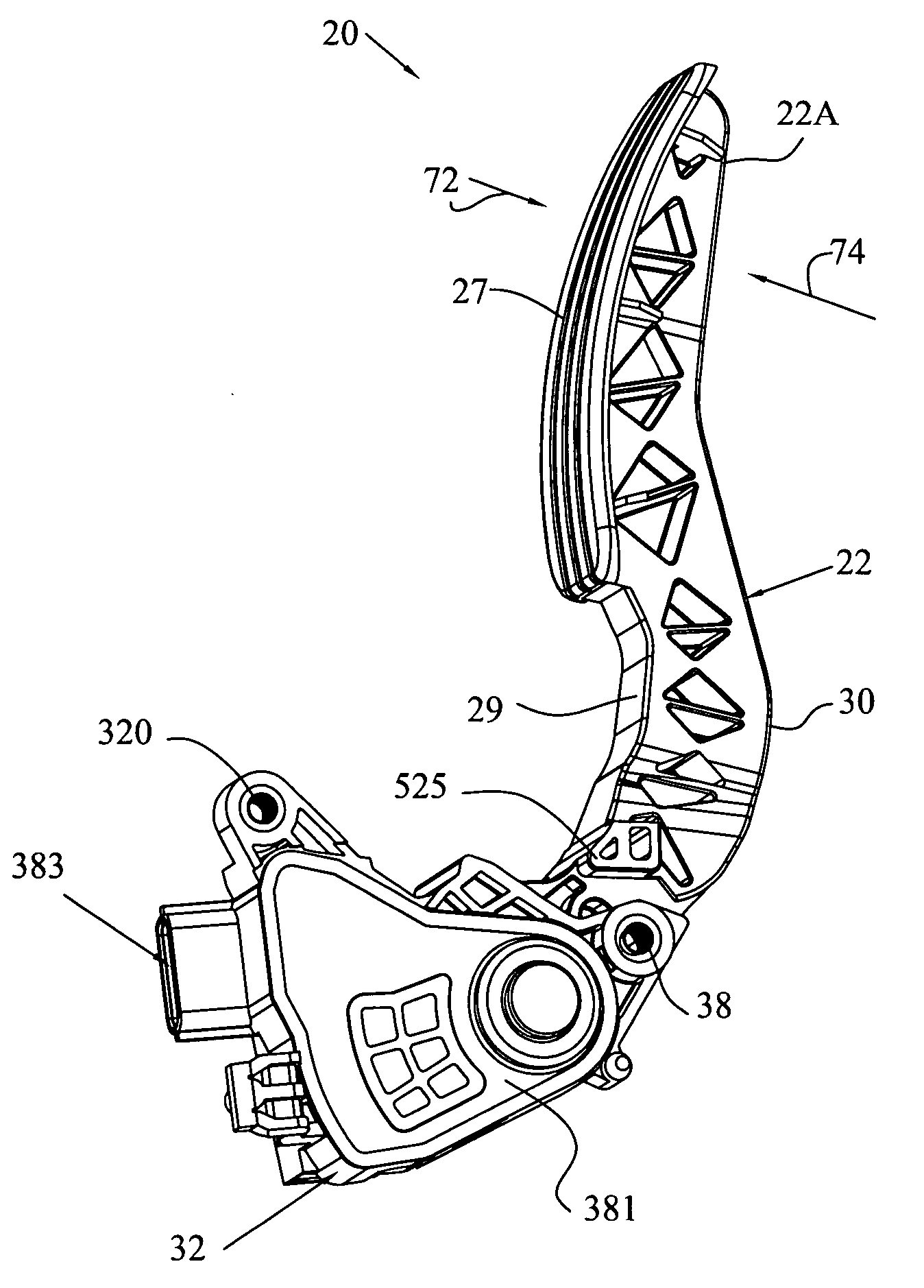
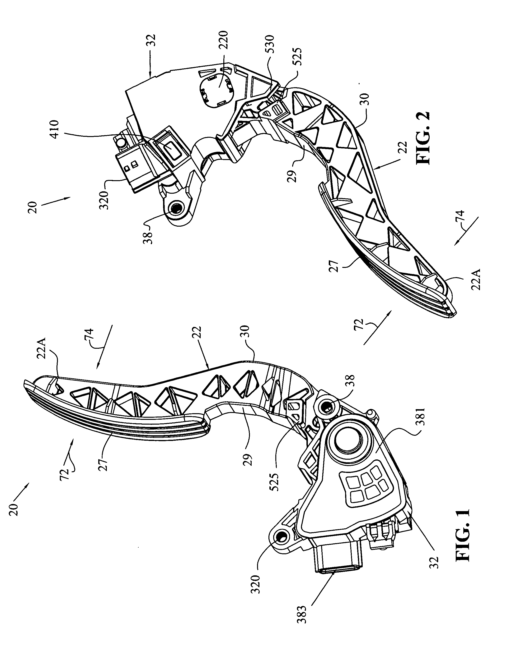
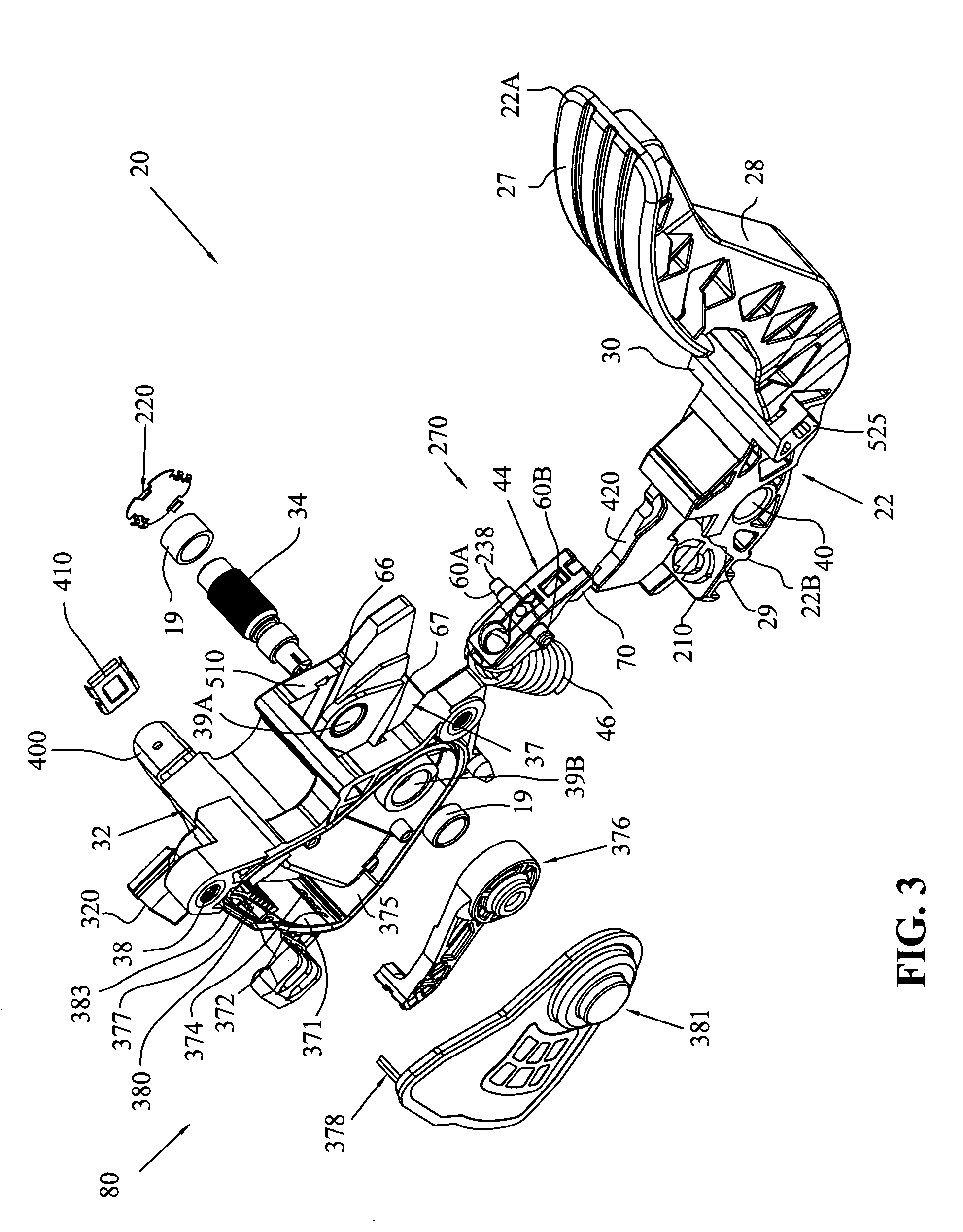
[0025] Referring to FIGS. 1-4, a non-contacting accelerator pedal assembly 20 according to the present invention includes a housing 32, a pedal arm 22 rotatably mounted to housing 32, a brake pad 44 and a bias spring device 46. The labels “pedal beam” or “pedal lever” also apply to pedal arm 22. Likewise, brake pad 44 may be referred to as a “body” or “braking lever.” Pedal arm 22 has ends 22A and 22B. A footpad 27 is located toward end 22A. Pedal arm end 22B has a drum portion 29 that presents a curved, W-shaped braking (or drag) surface 42 (best seen in FIGS. 5 and 6). Drum portion 29 also has a raised center ridge 43. A lever 210 extends from pedal ar...


PUM


Abstract

A pedal assembly that provides a hysteresis in pedal force-response upon actuation is provided. The pedal assembly includes a housing and a pedal arm that has an end. The end has a rotatable drum that defines a braking surface. The pedal arm is rotatably mounted to the housing. A lever extends from the second end. A brake pad is retained by the housing and has a contact surface that is substantially complementary to the braking surface. The brake pad is adapted to be engaged with the braking surface. A bias spring device is situated between the lever and the brake pad for urging the contact surface of the brake pad into frictional engagement with the braking surface of the drum. A sensor is coupled to the pedal arm to sense the position of the pedal arm.

Description

CROSS-REFERENCE TO RELATED AND CO-PENDING APPLICATIONS [0001] This application is a continuation in part of U.S. patent application Ser. No. 10 / 854,837, filed on May 27, 2004, and titled, “Accelerator Pedal Motorized Vehicle”. [0002] This application also claims the benefit of the filing date of U.S. Provisional Patent Application, Ser. No. 60 / 764,594, filed on 2 Feb. 2006, the contents of which are explicitly incorporated by reference, as are all references cited therein.FIELD OF THE INVENTION [0003] This invention relates to a pedal mechanism. In particular, the pedal may be an accelerator pedal in a vehicle. BACKGROUND OF THE INVENTION [0004] Automobile accelerator pedals have conventionally been linked to engine fuel subsystems by a cable, generally referred to as a Bowden cable. While accelerator pedal designs vary, the typical return spring and cable friction together create a common and accepted tactile response for automobile drivers. For example, friction between the Bowden...

Claims


Application Information

Patent Timeline
Patent Type & Authority Applications(United States)
IPC IPC(8): G05G1/14G05G1/38
CPCG05G1/38G05G5/03Y10T74/20528Y10T74/20534Y10T74/20888
Inventor CAMPBELL, ANDREW
Owner CTS CORP ELKHART
Why Eureka
Try Eureka