Ornament picket spacer for a railing system

a technology of railing system and picket, which is applied in the field of ornamental picket spacer for railing system, can solve problems such as undesirable systems

Inactive Publication Date: 2007-06-21
WALKER SIMON
View PDF24 Cites 23 Cited by
  • Summary
  • Abstract
  • Description
  • Claims
  • Application Information

AI Technical Summary

Problems solved by technology

These systems are undesirable, particularly in the residential railing indu

Method used


Image

  • Ornament picket spacer for a railing system
  • Ornament picket spacer for a railing system
  • Ornament picket spacer for a railing system

Examples


Embodiment Construction

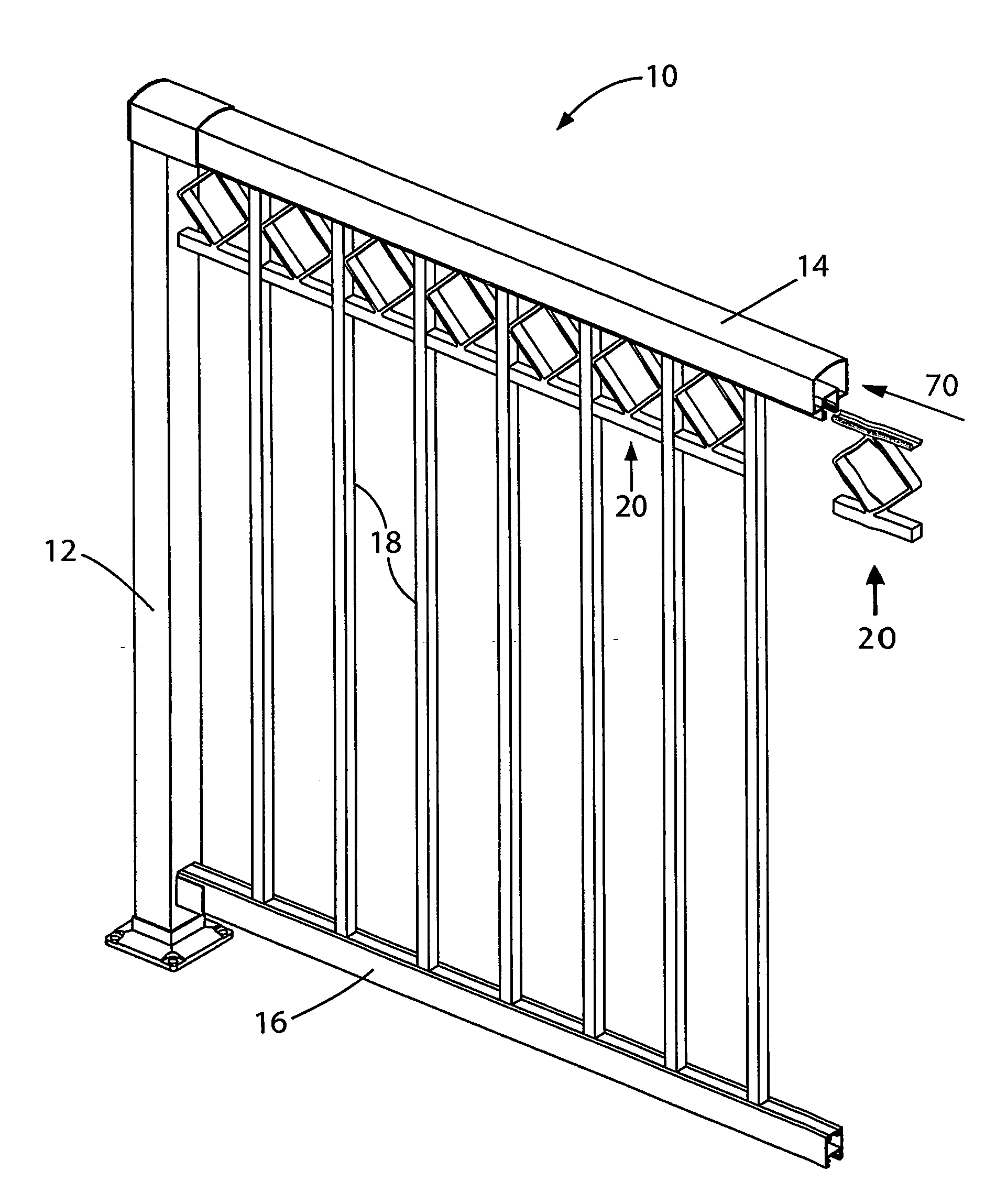
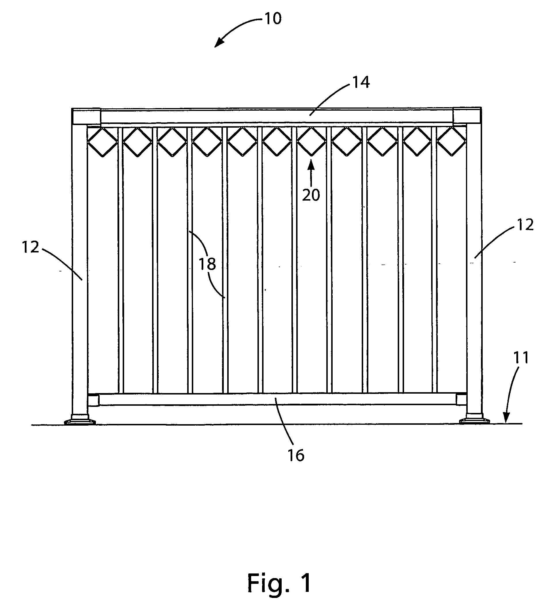
[0027]FIG. 1 shows a section of a picket and railing system generally indicated at 10 installed on a deck surface 11. The picket and railing system is generally formed by a pair of post supports 12, a handrail 14, a base rail 16 and a plurality of pickets 18. A plurality of ornamental picket spacers 20 are used to space apart the pickets 18 within the picket and railing system 10.

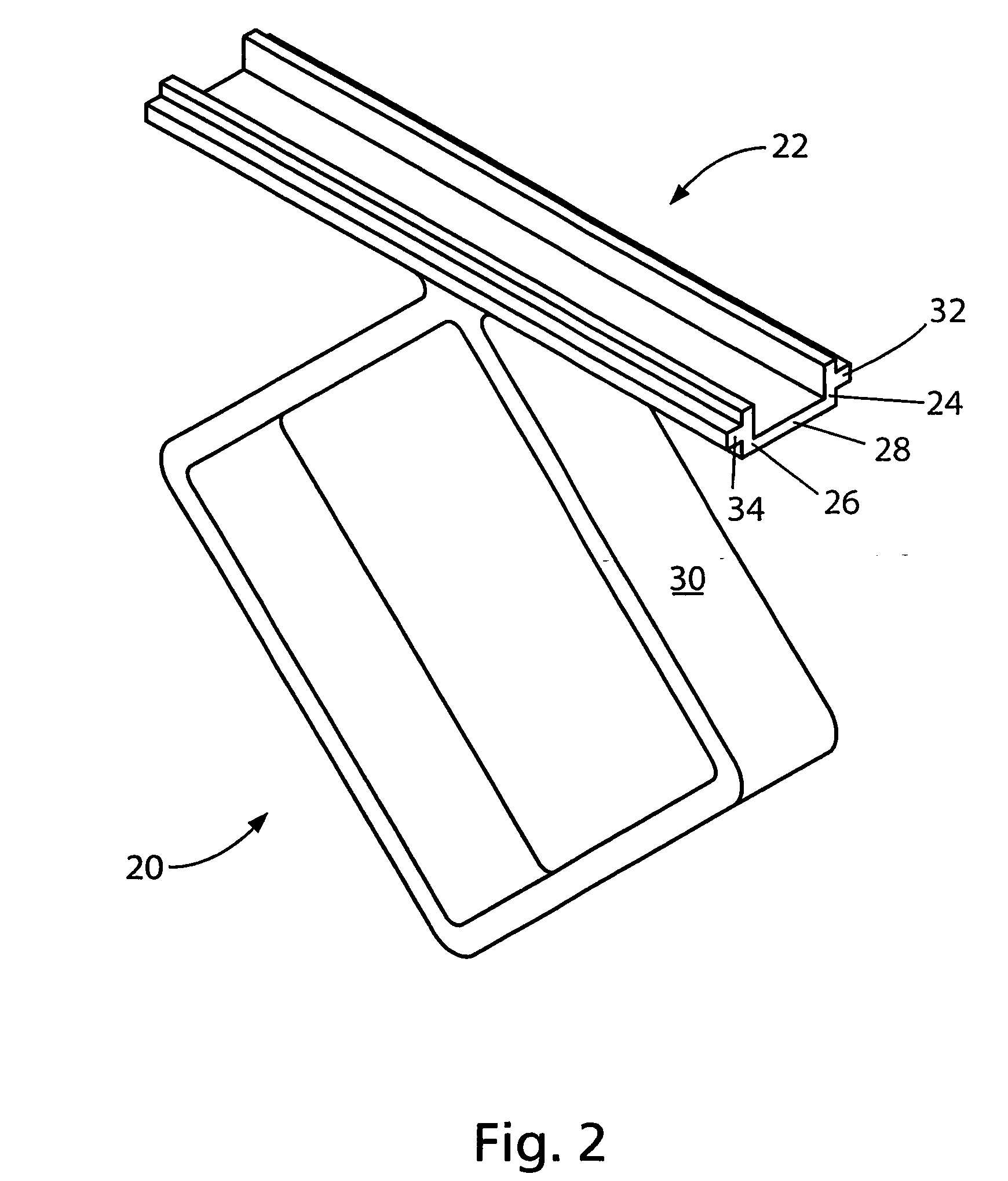
[0028] As illustrated in FIG. 2, the ornamental spacer 20 includes an elongated spacer member 22 having generally parallel sides 24, 26 and a wall 28 extending therebetween. An ornamental member 30 is connected to the wall 28. The generally parallel sides 24, 26 may extend perpendicularly to the wall 28 or may be curved. The generally parallel sides 24, 26 may include wings 32, 34, respectively for insertion into the railing system and may be formed as an integral part of the generally parallel sides. The wings 32, 34 may run the length of the elongated spacer member 22 as illustrated. Alternatively, as th...


PUM


Abstract

An ornamental picket spacer for a railing system. The spacer may include an elongated spacer member having generally parallel sides and a wall extending therebetween and an ornamental member connected to the wall. The generally parallel sides of the elongated spacer member may include wings for insertion into the railing system. The ornamental member may be a diamond or a circle or any other suitable shape.

Description

FIELD OF THE INVENTION [0001] The invention relates to the field of railings and in particular to an ornamental picket spacer for a railing system. BACKGROUND OF THE INVENTION [0002] Railing systems for any number of outdoor applications are well known. For example, residential decks, pool decks, playgrounds, etc., all utilize any number of conventional railing systems. Such railing systems are typically made of pressure treated lumber or aluminum particularly suited for outdoor use. [0003] Generally, in order to add an ornamental shape to the railing system, typical railing systems require professionals, for example, welders, to attach the ornamental shape to the railing systems. These systems are undesirable, particularly in the residential railing industry where homeowners frequently install or build their own railing systems. [0004] Accordingly, a need exists for providing a user with an improved system of adding an ornamental shape to a railing system and which overcomes the de...

Claims


Application Information

Patent Timeline
IPC IPC(8): E04H17/16E04F11/18
CPCE04F11/1842
Inventor WALKER, SIMON
Owner WALKER SIMON
Why Eureka
Try Eureka