Extruded Wall with Rib-Like Interior

a technology of extrusion wall and interior, which is applied in the direction of ceramic extrusion die, butter manufacturing, foundation engineering, etc., can solve the problems of regulating the amount of material extrusion, which can be challenging

Active Publication Date: 2007-06-21
UNIV OF SOUTHERN CALIFORNIA
View PDF38 Cites 66 Cited by
  • Summary
  • Abstract
  • Description
  • Claims
  • Application Information

AI Technical Summary

Problems solved by technology

Extruding structures that are strong with a minimum of material, varying the widths of the extruded structures, and regulating the amount of material that is extruded, however, can be challenging.

Method used


Image

  • Extruded Wall with Rib-Like Interior
  • Extruded Wall with Rib-Like Interior
  • Extruded Wall with Rib-Like Interior

Examples


Embodiment Construction

[0044] Illustrative embodiments of certain concepts will now be discussed. This discussion illustrates these concepts; it does not set forth all of their embodiments. Numerous other embodiments may be used in addition or instead, including those that are apparent from the discussion that is presented. Details that are apparent are also often omitted to save space or for more effective presentation.

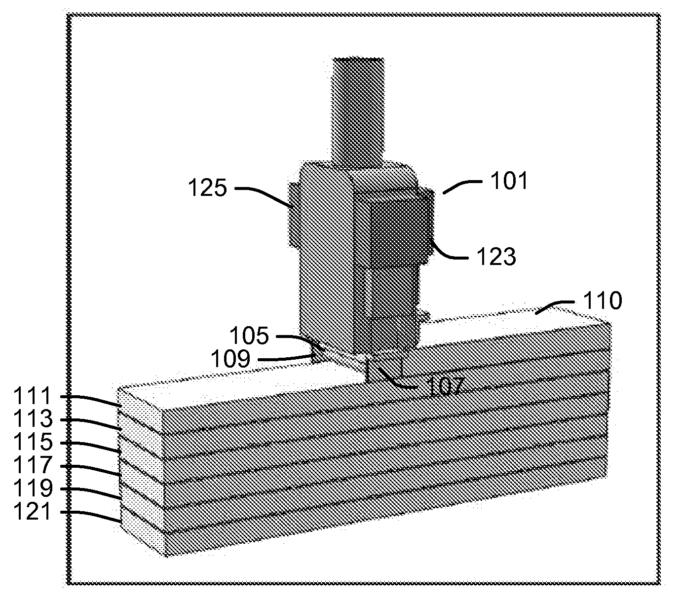
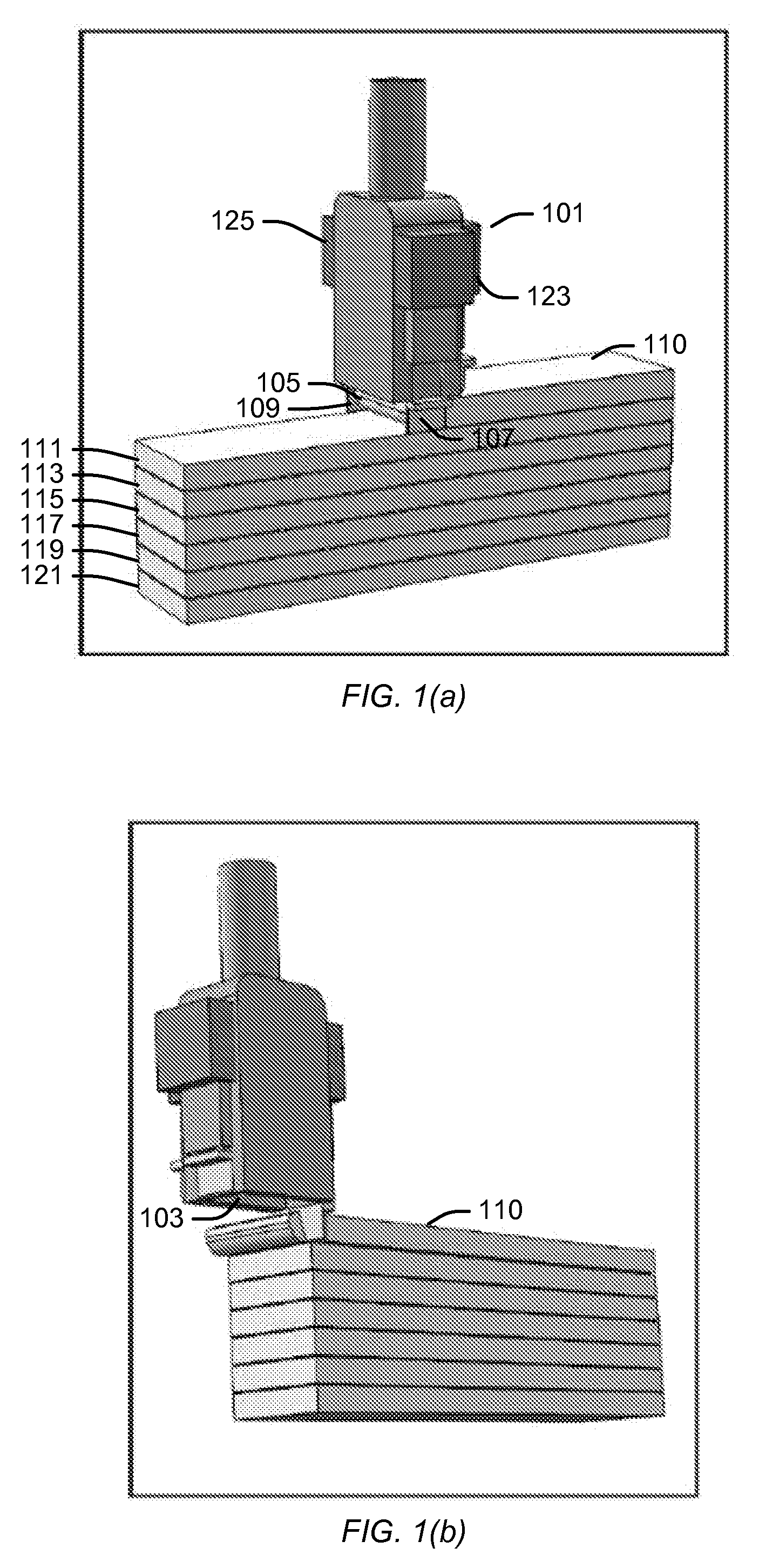
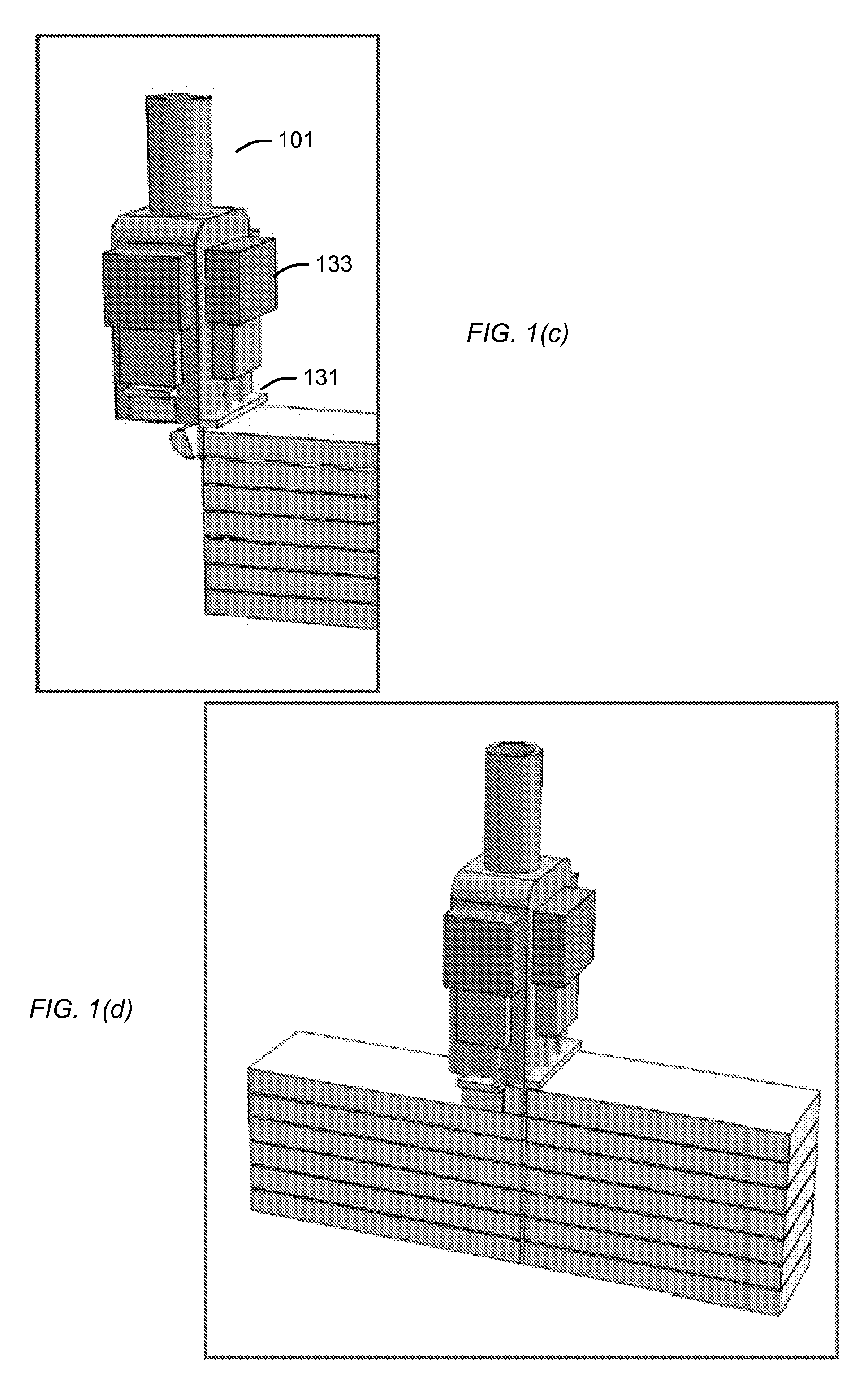
[0045] FIGS. 1(a)-(d) illustrate a contour crafting nozzle having a single outlet in operation. As shown in FIGS. 1(a)-(d), a contour crafting nozzle 101 may include an outlet 103 through which unhardened material 105 may be extruded. Trowels 107 and 109 may be controllably lowered for the purpose of smoothening the outer sides of the extrudates that are extruded, such as extrudates 110, 111, 113, 115, 117, 119 and 121. The trowels 107 and 109 may be extended and retracted by servomotors, such as servomotors 123 and 125, respectively. Solenoids, pneumatic actuators, or hydraulic actuators...


PUM

PropertyMeasurementUnit
frequencyaaaaaaaaaa
frequencyaaaaaaaaaa
widthaaaaaaaaaa

Abstract

A nozzle for extruding a surface may include a first outlet configured to controllably extrude a first extrudate of unhardened material, a second outlet configured to controllably extrude a second extrudate of unhardened material that is separated from the first extrudate, a third outlet configured to extrude a third extrudate of unhardened material between the first and the second extrudates, and a controller. The third outlet may have a width that is substantially less than the distance between the first and second extrudates. The controller may be configured to cause the third extrudate to repeatedly traverse between the first and second extrudates and / or to cause the third extrudate to leave a plurality of substantial and separated spaces between the first and second extrudates.

Description

CROSS-REFERENCE TO RELATED APPLICATIONS [0001] This application is based upon and claims priority to U.S. Provisional Patent Ser. No. 60 / 730,560, entitled “Contour Crafting Nozzle and Features for Fabrication of Hollow Structures,” Attorney Docket No. 28080-190, filed Oct. 26, 2005. This application is also related to U.S. patent application Ser. No. 10 / 760,963, entitled “Multi-Nozzle Assembly for Extrusion of Wall,” Attorney Docket No. 28080-115, filed Jan. 20, 2004, which claims priority to and incorporates by reference U.S. Provisional Application Ser. No. 60 / 441,572, entitled “Automated Construction,” Attorney Docket No. 28080-097, filed Jan. 21, 2003. This application is also related to U.S. patent application Ser. No. 11 / 040,401, entitled “Robotic Systems for Automated Construction,” Attorney Docket No. 28080-149, filed Jan. 21, 2005, U.S. patent application Ser. No. 11 / 040,602, entitled “Automated Plumbing, Wiring, and Reinforcement,” Attorney Docket No. 28080-154, filed Jan....

Claims


Application Information

Patent Timeline
Patent Type & Authority Applications(United States)
IPC IPC(8): E04B1/16B29C47/00B29C48/06B29C48/14B29C48/30
CPCB28B1/16B28B3/2636B28B11/042B29C47/0016E04B1/3505B29C67/0055B29K2105/04B29K2995/0002B29C47/0071E04G2021/049B29C64/106B28B1/001B29C48/06B29C48/14E04G21/0463
Inventor KHOSHNEVIS, BEHROKH
Owner UNIV OF SOUTHERN CALIFORNIA
Why Eureka
Try Eureka