Loudspeaker array audio signal supply apparartus

a technology of audio signal supply and loudspeaker array, which is applied in the direction of transducer casing/cabinet/support, stereophonic circuit arrangement, electrical transducer, etc., can solve the problems of large volume, deterioration of audio quality around the loudspeaker in the location off the front of the loudspeaker, and inability to turn up high volume, etc., to achieve efficient directivity and wide directivity

Active Publication Date: 2007-07-19
YAMAHA CORP
View PDF46 Cites 44 Cited by
  • Summary
  • Abstract
  • Description
  • Claims
  • Application Information

AI Technical Summary

Benefits of technology

[0023] As described above, according to the present invention, a wide directivity can be provided, and an effi

Problems solved by technology

These large, thin televisions used to have problems resulting from small viewing angles.
However, for a large, thin television that employs the above described loudspeakers, a problem is that the audio quality around the loudspeakers is deteriorated in location of

Method used


Image

  • Loudspeaker array audio signal supply apparartus
  • Loudspeaker array audio signal supply apparartus
  • Loudspeaker array audio signal supply apparartus

Examples


Embodiment Construction

[0035] Before the individual modes according to the present invention are described, the basic theory of the present invention will first be explained.

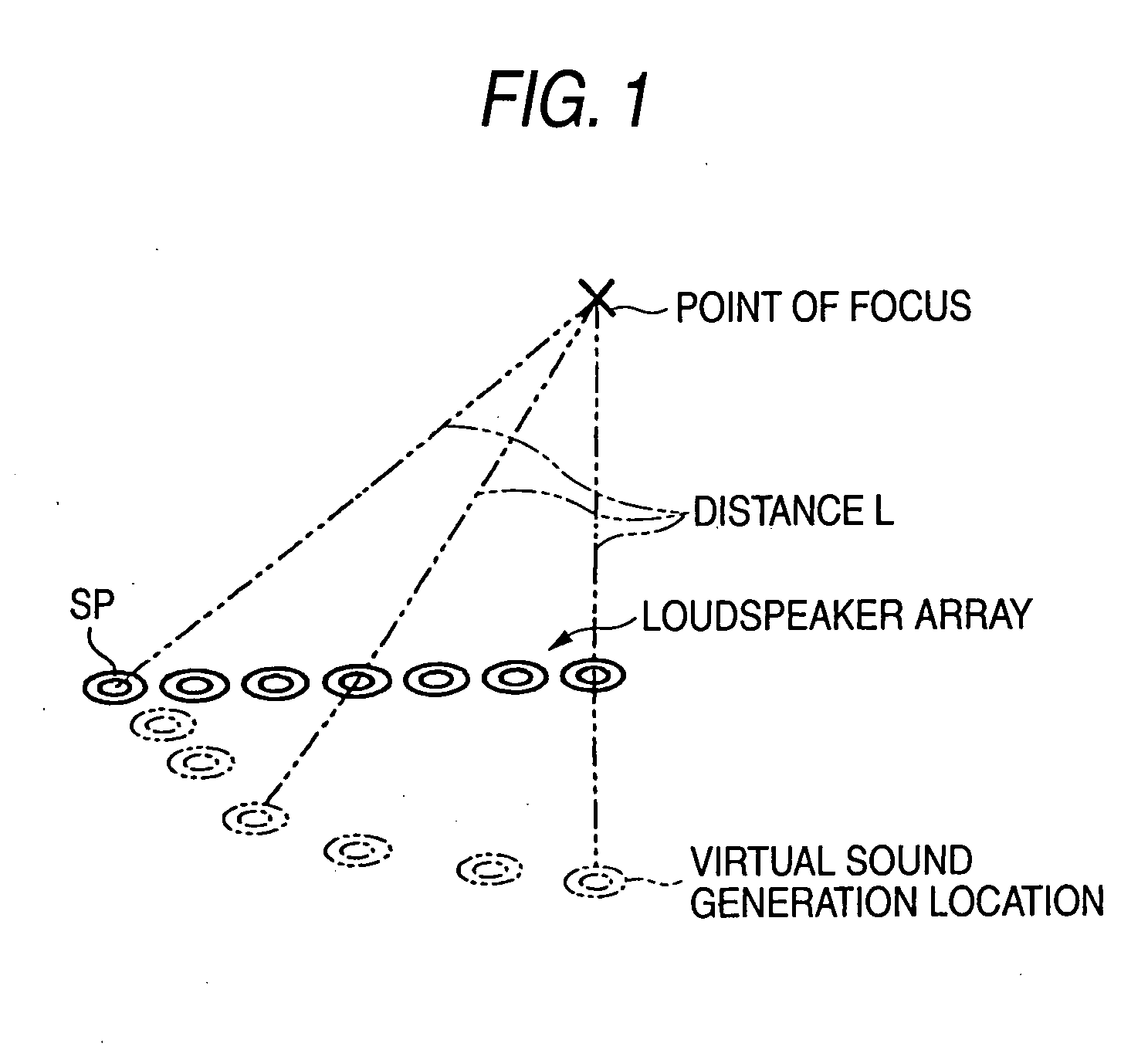
[0036]FIG. 1 is a diagram for explaining directivity control of a delay array type that employs a loudspeaker array (constituted by a plurality of small loudspeaker units SP) according to a first basic theory. When the amount of a delay, which is consonant with a difference between the path from the center of the loudspeaker array to a specific point (point of focus) in space and the path from the loudspeaker units SP to the point of focus, is given to an audio signal that is to be supplied to the loudspeaker units SP, sound waves output by the individual loudspeaker units SP reach the point of focus at the same time. That is, the loudspeaker units SP can be regarded as being located at virtual sound generation locations (locations where distances L from the point of focus are equal) indicated by broken lines in FIG. 1, and the sound...


PUM


Abstract

A first directivity parameter to provide a narrow directivity and a second directivity parameter to provide a wide directivity are preset for a directivity control apparatus to control the directivity of an array loudspeaker system. The directivity control apparatus selects either the first directivity parameter or the second directivity parameter in accordance with an instruction that is entered through an operating unit to select the directional characteristic of a loudspeaker array. Then, based on the selected directivity parameter, the directivity control apparatus generates delay control information, to be supplied to a delay circuit, and generates gain control information, to be supplied to a weighting unit.

Description

TECHNICAL FIELD [0001] The present invention relates to an audio signal supply apparatus that supplies an audio signal, such as a sound, to a loudspeaker array that is constituted by a plurality of loudspeaker units. BACKGROUND ART [0002] In recent years, large, thin televisions, such as plasma televisions and liquid crystal televisions, have rapidly spread to average homes. These large, thin televisions used to have problems resulting from small viewing angles. However, through various improvements, the problems with viewing angles have been largely eliminated, and when televisions are installed in a spacious room, we can view scenes from various locations. While much consideration has been given to improving pictures, as described above, sounds have not been much taken into account. For example, many loudspeakers employed for large, thin televisions are a combination of conventional loudspeakers, such as two-way loudspeakers, that have dipole type directional characteristics (see,...

Claims


Application Information

Patent Timeline
IPC IPC(8): H04R1/02H04R3/00H04R1/40H04R5/04H04S1/00H04S7/00
CPCH04R1/403H04R5/04H04R2430/20H04R2205/041H04R2205/022
Inventor KONAGAI, YUSUKE
Owner YAMAHA CORP
Why Eureka
Try Eureka