
Fabric for end fray resistance and protective sleeves formed therewith and methods of construction

a technology of end fraying resistance and protective sleeves, applied in the direction of pedestrian/occupant safety arrangements, braids, vehicular safety arrangements, etc., can solve the problems of reducing the useful life of the sleeve, affecting the operation of the sleeve, and damage to the wire harness, so as to prevent the sleeve from fraying

Active Publication Date: 2007-07-19
FEDERAL MOGUL WORLD WIDE LLC
View PDF33 Cites 80 Cited by
  • Summary
  • Abstract
  • Description
  • Claims
  • Application Information

AI Technical Summary

Benefits of technology

[0008]According to another presently preferred textile sleeve construction, a substrate of filamentary members are interlaced with one another, wherein at least some of the filamentary members are monofilaments having a core of heat-settable polymeric material and an outer sheath of heat-fusible polymeric material. The outer sheaths of the monofilaments are heat-fused to one another along at least a portion of the sleeve, and preferably adjacent its opposite ends to prevent the sleeve from fraying at its ends, particularly when the sleeve is cut to length.

Problems solved by technology

For example, wire harnesses may be subjected to excessive heat or vibrations during vehicle operation which can damage the wire harness and impair its operation and reduce its useful life.
Apart from being aesthetically unpleasing, the frayed, protruding filaments can contaminate the tubes, hoses or wire harnesses about which the sleeve is disposed by interfering with the ability to properly connect end fittings or couplings with their mating parts.

Method used


Image

  • Fabric for end fray resistance and protective sleeves formed therewith and methods of construction
  • Fabric for end fray resistance and protective sleeves formed therewith and methods of construction
  • Fabric for end fray resistance and protective sleeves formed therewith and methods of construction

Examples


Embodiment Construction

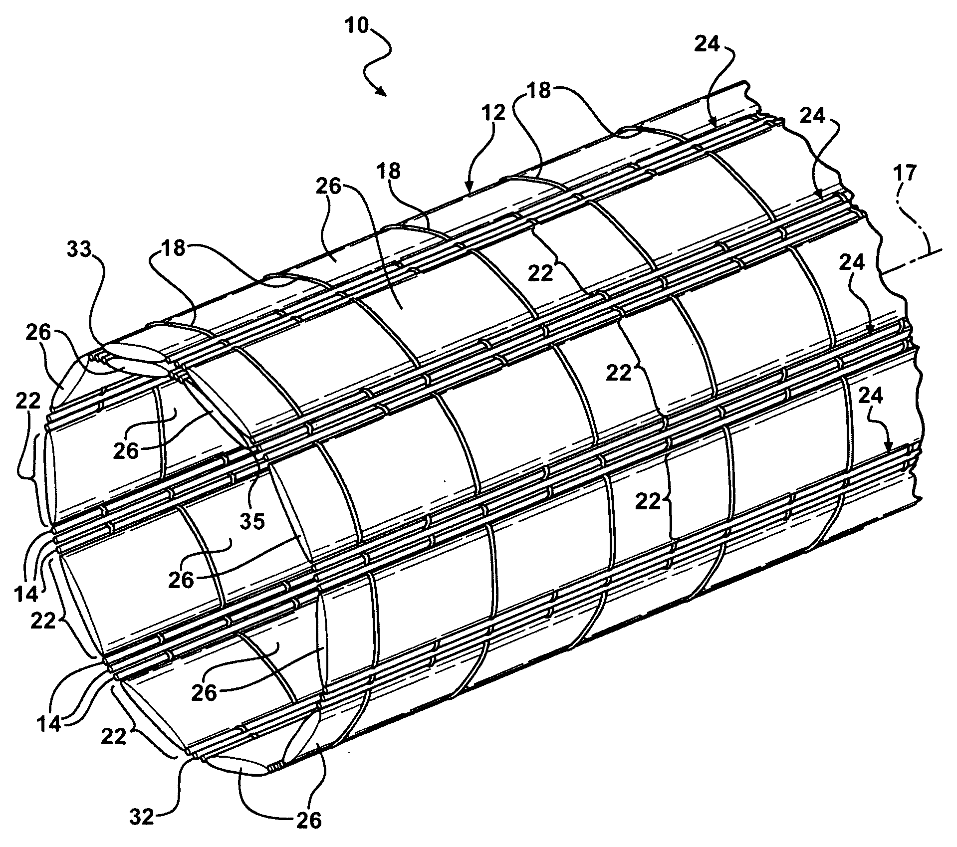
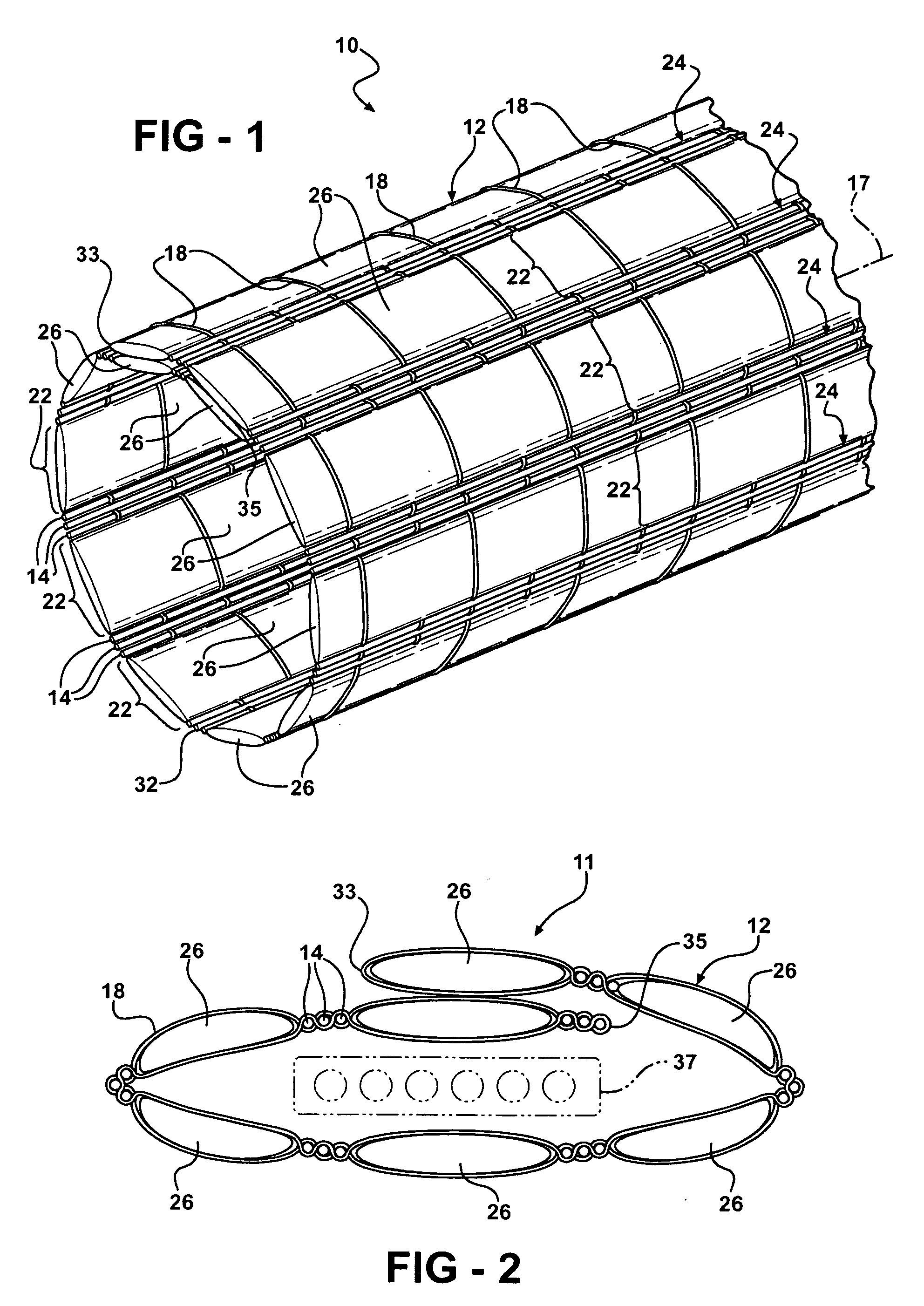
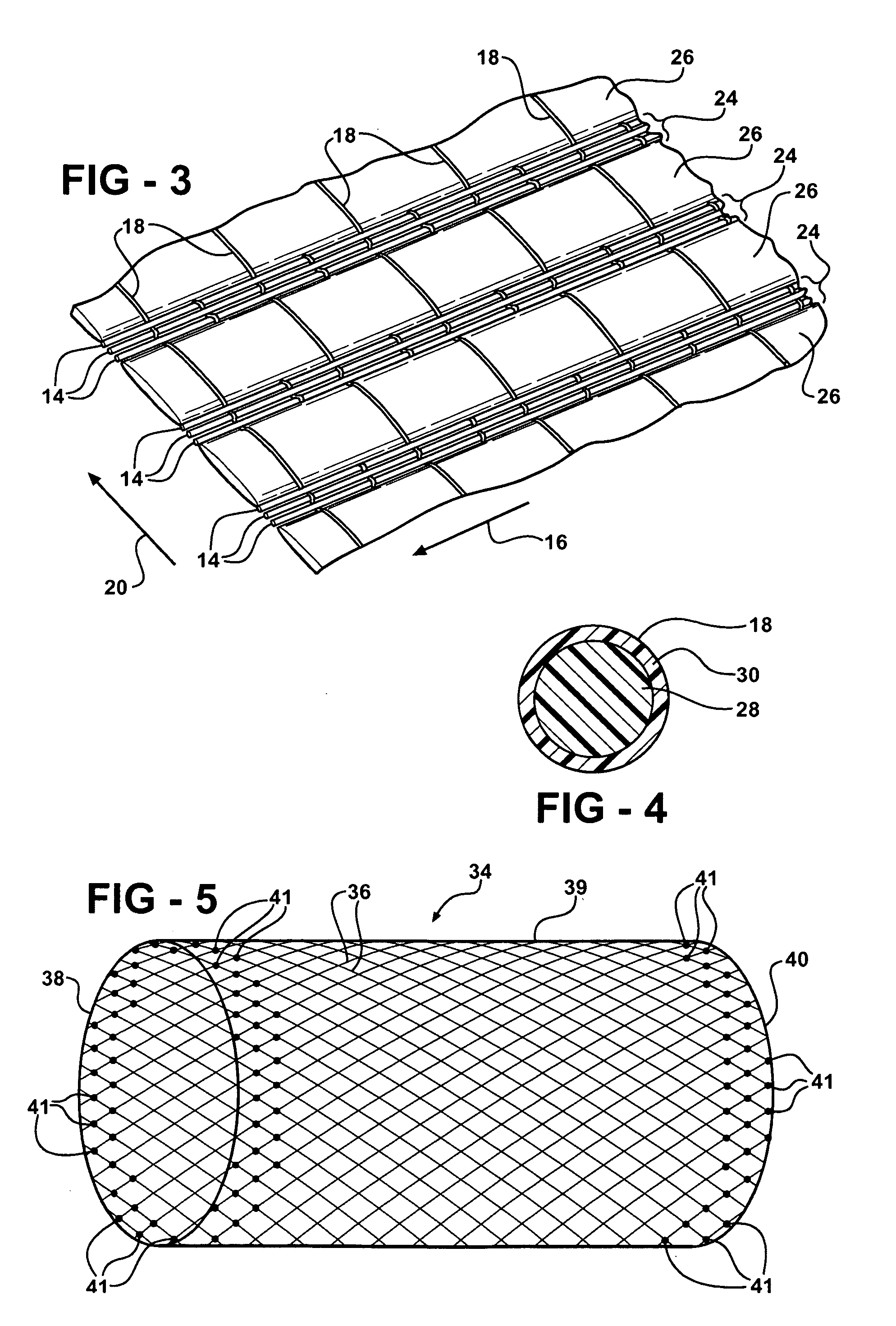
[0022]Referring in more detail to the drawings, FIGS. 1 and 2 illustrate protective textile sleeves 10, 11 according to presently preferred embodiments, wherein the sleeves 10, 11 are similar, however the sleeve 10 is generally cylindrical in lateral cross-section, while the sleeve 11 is generally oval or flat in lateral cross-section. Given the similarities, other than finished shape, the sleeves are generally the same, and thus, the same reference numerals are used to identify their features. The sleeves 10, 11 include a fabric, also referred to as a substrate 12, wherein the substrate has interlaced yarns that can be woven or knitted. By way of example and without limitations, the illustrated sleeves 10, 11 are woven. As best shown in FIG. 3, the substrate 12 includes a plurality of first filamentary members 14 that are oriented in a first direction indicated by arrow 16. For a woven substrate, the arrow 16 corresponds to the warp direction, which corresponds to a longitudinal ax...


PUM

PropertyMeasurementUnit
Lengthaaaaaaaaaa
Shapeaaaaaaaaaa
Electrical conductoraaaaaaaaaa

Abstract

An elongated protective textile sleeve for protecting elongate members and methods of constructing a fabric substrate therefore. The fabric substrate has a plurality of filamentary members either woven, knitted or braided with one another. At least some of the filamentary members of the substrate extend to cut edges and are fabricated of a multi-component material that includes a core of a first polymeric material and an outer sheath of a second polymeric material. The outer sheath is heat-fusible and the inner core is heat-settable. The outer sheaths of the filamentary members are heat fused at least in the regions near the cut edges to keep the cut edges from fraying or the filamentary members from pulling out of the substrate. The core is heat set to form the desired shape of the protective sleeve.

Description

CROSS-REFERENCE TO RELATED APPLICATION[0001]This application claims the benefit of U.S. Provisional Patent Application No. 60 / 760,057, filed Jan. 19, 2006, which is incorporated herein by reference in its entirety.BACKGROUND OF THE INVENTION[0002]1. Technical Field[0003]This invention relates generally to textile fabrics and their methods of construction, and more particularly to textile fabrics of the type incorporating engineered filamentary plastics materials that are shaped to form protective sleeves for elongate members.[0004]2. Related Art[0005]Wiring harnesses, hoses, tubing and the like often must endure harsh environmental conditions in automotive, industrial, aerospace, marine and other applications. For example, wire harnesses may be subjected to excessive heat or vibrations during vehicle operation which can damage the wire harness and impair its operation and reduce its useful life. It is common to cover wire harnesses with protective sleeving to protect them from the a...

Claims


Application Information

Patent Timeline
IPC IPC(8): B60R21/16B32B1/08D03D15/567
CPCB32B5/26Y10T428/1355B32B5/028B32B5/08B32B5/10B32B5/12B32B7/10B32B15/14B32B27/12B32B27/36B32B1/08D03D3/02D03D9/00D03D15/0027D03D15/04D10B2401/041H02G3/0481Y10T428/1362B60R2021/23509D04C1/02D10B2505/12Y10T442/3154Y10T442/159D03D15/567D03D15/47D03D15/587D03D1/0043B32B5/02F16L11/00
Inventor SELLIS, TIMOTHY DAVIDTAULBEE, MATTHEW RAYSCHREPPLE, WILLIAM J.MARKS, PHILIP EDWARD
Owner FEDERAL MOGUL WORLD WIDE LLC
Learn More