High-start spring energized stapler

a stapler and high-start technology, applied in the field of spring-actuated staplers, can solve the problems of no functional mechanism disclosed to reset the striker, and no linkage described to enable the reset spring to lift the striker against the force of the power spring, so as to improve the use of the handle and increase the leverage

Active Publication Date: 2007-08-02
WORKTOOLS
View PDF21 Cites 39 Cited by
  • Summary
  • Abstract
  • Description
  • Claims
  • Application Information

AI Technical Summary

Benefits of technology

[0004] In a preferred embodiment of the present invention, a high start, spring actuated stapler provides a compact stapler that combines enhanced handle travel for greater leverage with a separately movable spring / cage subassembly to preload the power spring. The cage may be pivotably attached to the housing at a location separate from the pivotable attachment of the handle. A striker alternates between an initial position above a staple track and a lower-most position in front of the staple track. A power spring is deflected to store energy by the motion of the handle. At a predetermined position of the handle, the striker is released to accelerate to the lower-most position by urging of the power spring.
[0005] The striker moves a minimum vertical distance required to drive staples while the handle, at a handle pressing area, moves substantially farther than the striker to achieve increased leverage and lower actuation force. According to various embodiments, a lever links the handle to a power spring or a spring / cage subassembly to provide the added leverage for the handle, and for added leverage in moving a release latch. According to a further embodiment, the handle includes a movable or slotted pivot attachment near a rear of the housing to provide enhanced travel at the front pressing area of the handle.
[0006] In various alternative embodiments, release mechanisms include a lever pivotably and slidably attached in the housing. The lever pivots out of engagement with the striker and slides rearward in a reset action. Further release mechanisms use separately movable latches. For example, a release latch is movably fitted in the housing and is moved out of engagement with the striker or power spring by urging from the lever. The lever does not directly contact the striker. A further embodiment release latch is urged out of engagement by contact with the handle. The various embodiment release latches may be mounted in front of or behind the striker. With the release latch in front of the striker, the power spring may pass behind the latch as the spring moves. The shape of the latch may thus be less constrained by a requirement to clear the power spring and possibly an associated lever. With the latch to the rear of the striker, the power spring can normally pass through a slot of the latch or beside the latch as the spring moves.

Problems solved by technology

However, in such conventional high start designs, the striker is driven directly by the handle with no power spring to store energy that could be used to drive the striker.
However, no functional mechanism to reset the striker is disclosed.
Instead, the striker is somehow lifted by a very stiff reset spring, yet no linkage is described to enable a reset spring to lift the striker against the force of the power spring.

Method used


Image

  • High-start spring energized stapler
  • High-start spring energized stapler
  • High-start spring energized stapler

Examples


Embodiment Construction

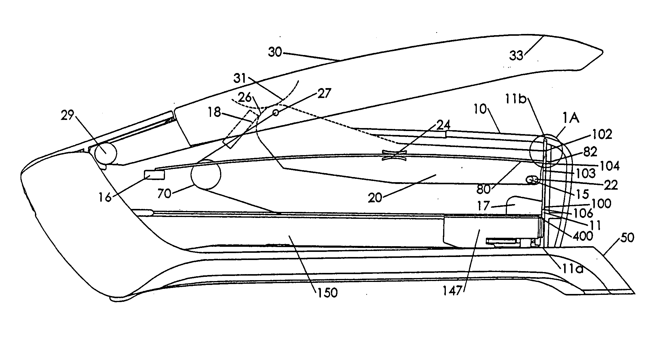
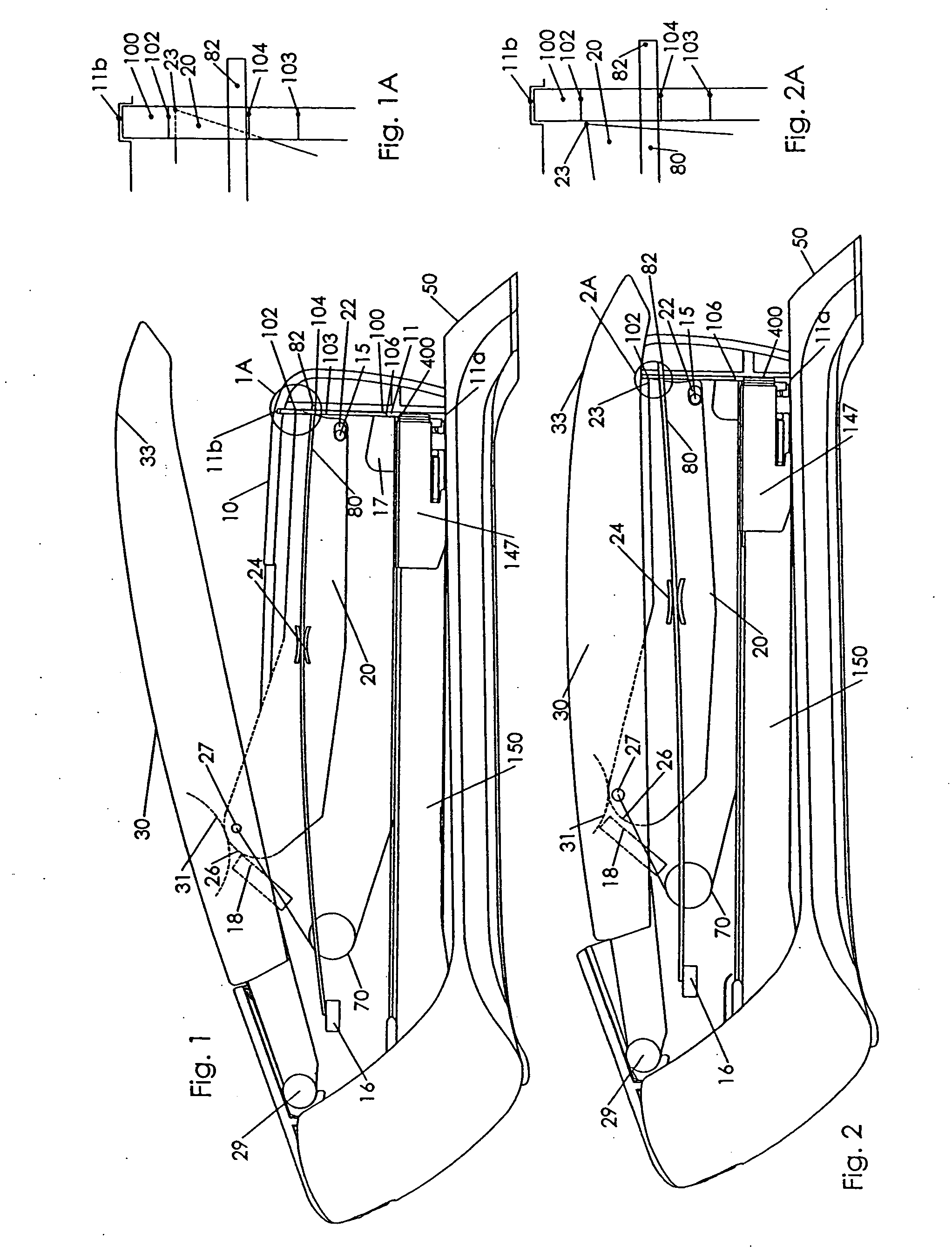
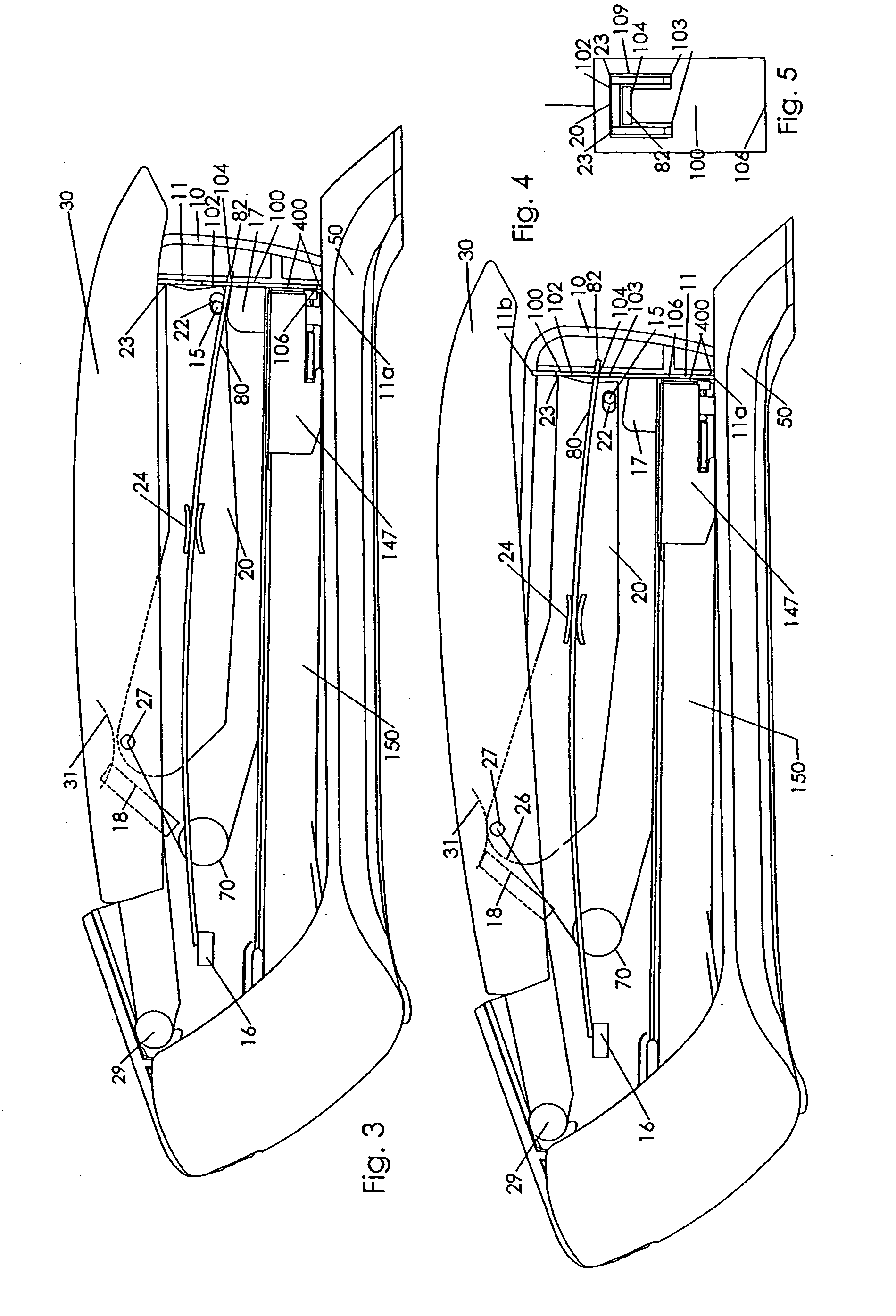
[0036] FIGS. 1 to 5 show one preferred embodiment of a high start stapler. In the side elevational views of FIGS. 1 and 2, one half of the body has been removed to expose the internal workings. In the some of the drawing figures, the base has been omitted for simplicity and clarity.

[0037] An upper body of the stapler including housing 10 is pressed against base 50. Base 50 includes a staple forming anvil (not shown) to fold staples behind a stack of sheet media to be stapled, such as papers (not shown). Any of the staplers of the present invention may also be used as a tacker to install staples into a work surface if the base is rotated away or not used. Lever 20 provides a link between handle 30 and power spring 80. Lever 20 is preferably an elongated U-channel having a rounded back end and an angled leading edge, but a simple flat plate may also be used. Handle 30 has an elongated ergonomic shape and is hinged at its back end against housing 10 at handle pivot 29, considered the ...


PUM


Abstract

A spring energized stapler includes a “high start” design wherein a striker has a rest position above the staple track. A handle is pressed to energize a power spring while the striker remains stationary. At a predetermined position of the handle, the striker is released to eject a staple. A subassembly of a cage and the power spring provides a preload to the power spring in the rest position. The subassembly is separately movable from the handle to allow a handle pressing end to move farther than the striker's distance of travel. The handle includes a movable pivot location to enable enhanced motion of the handle pressing end. Alternatively, an optional lever links the striker to the power spring to provide leverage upon the power spring. A release latch may be mounted in front of the striker to be engaged by the lever or the handle.

Description

FIELD OF THE INVENTION [0001] The present invention relates to spring powered desktop staplers. More precisely, the present invention relates to improvements to a spring-actuated stapler with a striker having an initial “high start” position. BACKGROUND OF THE INVENTION [0002] Spring powered staplers and staple guns operate by driving a striker with a power spring. The striker ejects a staple by impact blow. In a desktop stapler, the staple is ejected into an anvil of a pivotably attached base. Two general principles are used. In the first design, the striker has an initial position in front of a staple track. The striker is lifted against the force of the power spring to a position above the staple track. The striker is released to impact and eject the staple. This design may be referred to as a “low start” stapler. A second design uses a “high start” position. That is, the striker has an initial position above the staples loaded on the staple feed track. The power spring is deflec...

Claims


Application Information

Patent Timeline
Patent Type & Authority Applications(United States)
IPC IPC(8): B25C5/06
CPCB25C5/11B25C5/0242
Inventor MARKS, JOEL S.
Owner WORKTOOLS
Why Eureka
Try Eureka