Motor rotor structure

Inactive Publication Date: 2007-08-09
SUNONWEALTH ELECTRIC MACHINE IND
View PDF13 Cites 0 Cited by
  • Summary
  • Abstract
  • Description
  • Claims
  • Application Information

AI Technical Summary

Benefits of technology

[0010] The lubricating oil leaving an axial hole of a bearing in the axial tube could not escape from the axial tube. The lubricating oil leaving the axial hole impacts the bottom face and then flows back into the bearing along the bottom face. Outflow and loss of the lubricating oil are thus avoided.

Problems solved by technology

Since a large gap exists between the upper end of the axial tube 11 and the axial seat 22, the lubricating oil is liable to exit the motor via the gap, resulting in low rotational efficiency, generation of operational noise, and shortening of life of the motor.

Method used


Image

  • Motor rotor structure
  • Motor rotor structure
  • Motor rotor structure

Examples


first embodiment

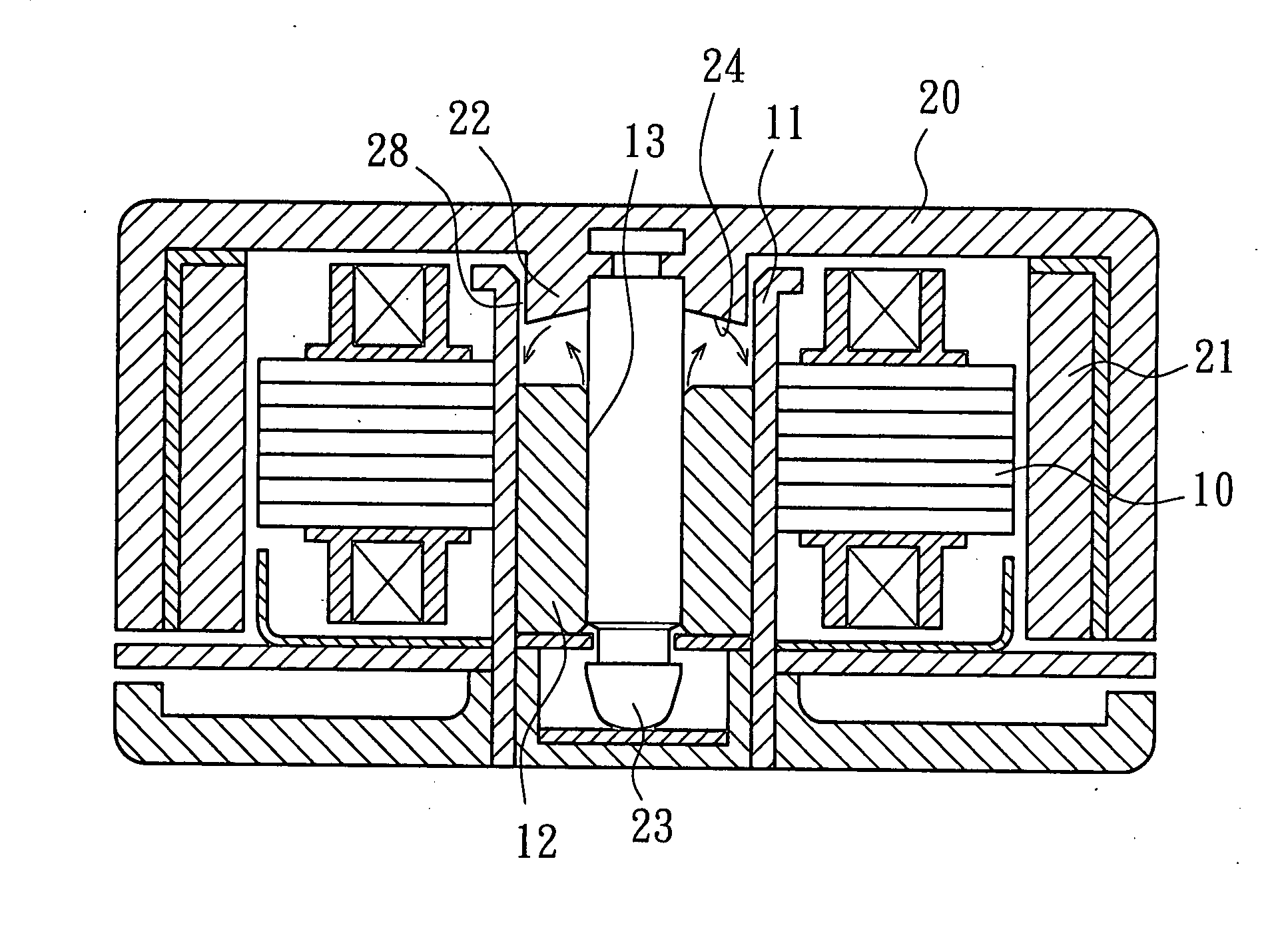
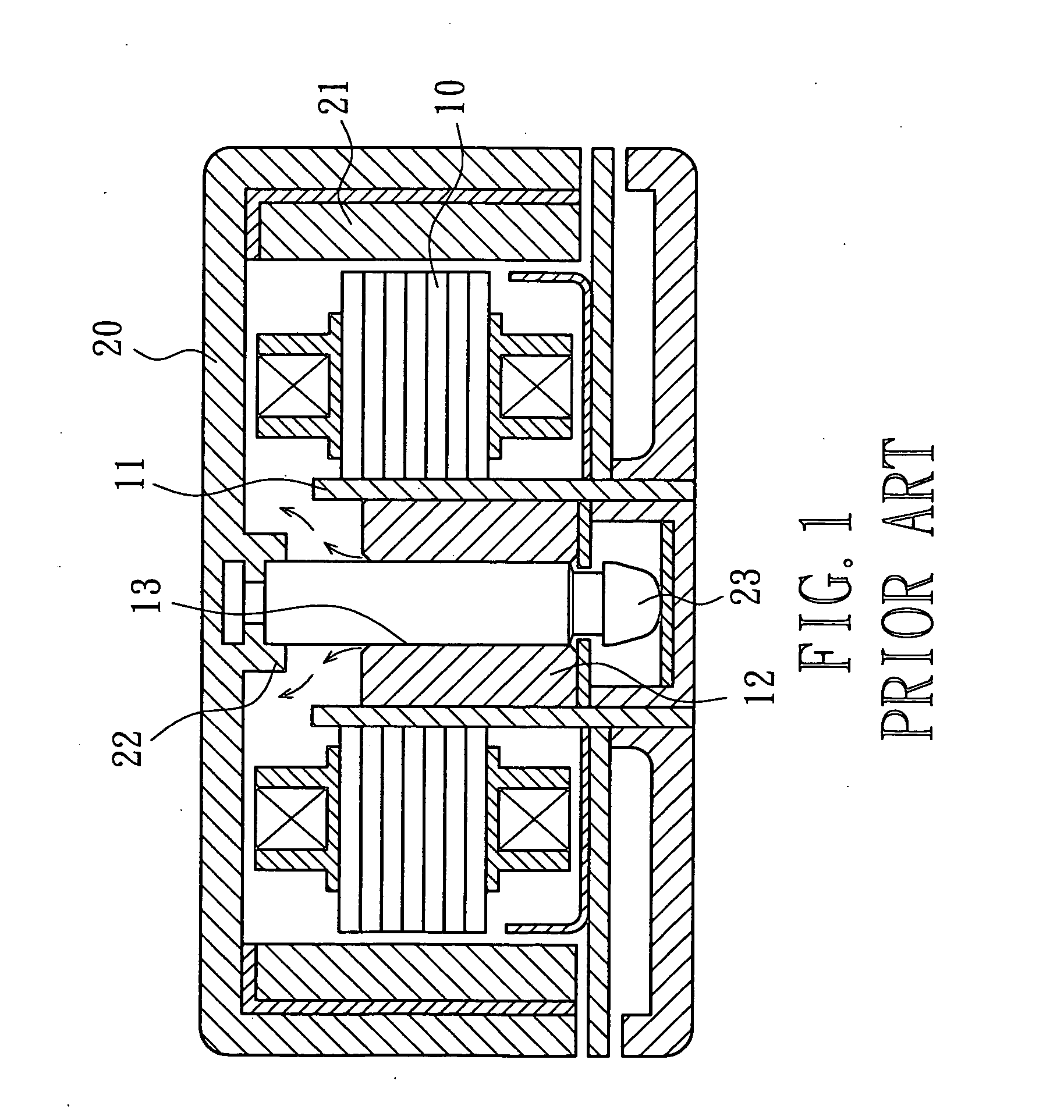
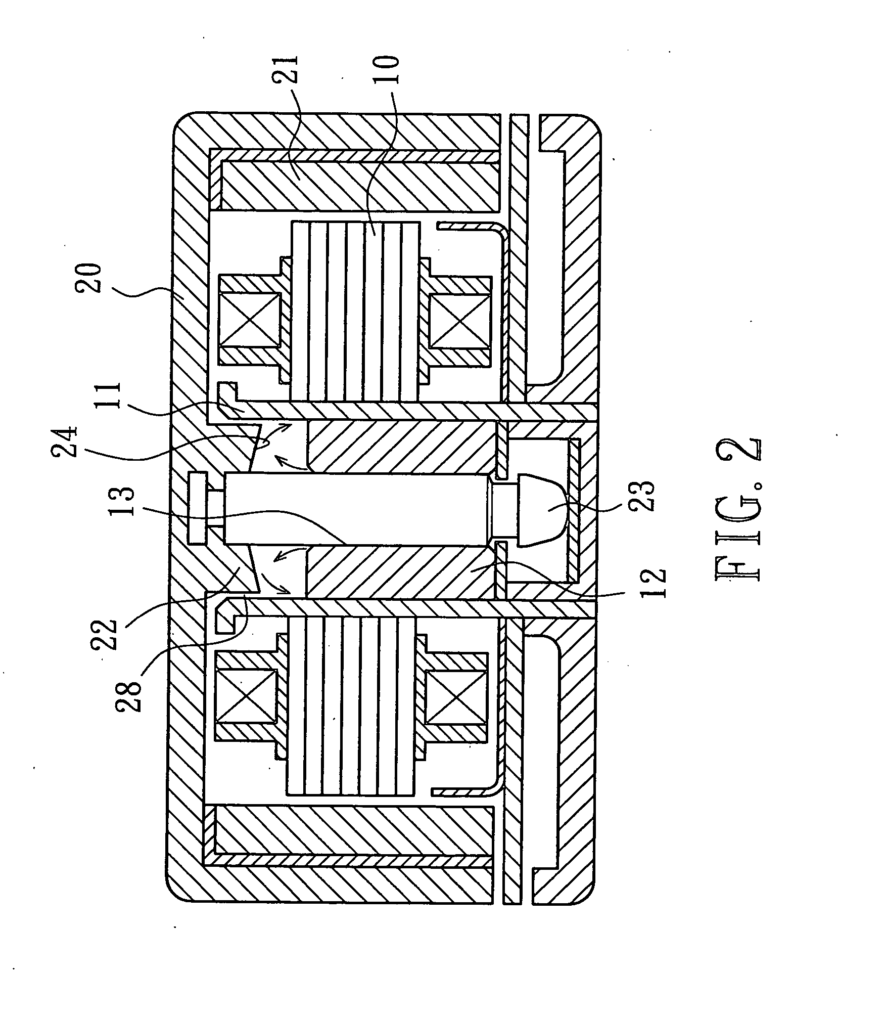
[0022]FIG. 2 illustrates a motor with the present invention. The motor comprises a stator 10 and a rotor 20. The stator 10 includes an axial tube 11 in which a bearing 12 is received. The bearing 12 is preferably selected from an oily bearing and includes a central axial hole 13 in the form of a through-hole.

[0023] The rotor 20 is mounted around and covers the stator 10. A permanent magnet 21 is fixed to an inner circumferential wall of the rotor 20 and faces the stator 10. An axial seat 22 protrudes from a center of the rotor 20 for coupling with a shaft 23. The shaft 23 of the rotor 20 is rotatably extended through the axial hole 13 of the bearing 12.

[0024] The axial seat 22 extends into the axial tube 11 of the stator 10. Further, a gap 28 smaller than 1 mm exists between the axial seat 22 and an inner circumferential wall of the axial tube 11. Nevertheless, the axial seat 22 is not in contact with the inner circumferential wall of the axial tube 11.

[0025] By such an arrangemen...

second embodiment

[0027]FIG. 3 shows the invention, wherein the bottom face 24 is a conic face with a central stepped portion 25 to provide a difference in height from a center of the shaft 23 to a circumferential edge of the bottom face 24. Similarly, the lubricating oil leaving the axial hole 13 of the bearing 12 could not escape from the axial tube 11. The lubricating oil leaving the axial hole 13 impacts the conic bottom face 24 with a central stepped portion 25 and then flows back into the bearing 12 along the conic face. Outflow and loss of the lubricating oil are thus avoided.

third embodiment

[0028]FIG. 4 shows the invention, wherein the bottom face 24 includes an annular groove 26 defined by an arcuate wall to provide a difference in height from a center of the shaft 23 to a circumferential edge of the bottom face 24. Similarly, the lubricating oil leaving the axial hole 13 of the bearing 12 could not escape from the axial tube 11. The lubricating oil leaving the axial hole 13 impacts the bottom face 24 with an annular groove 26 and then flows back into the bearing 12 along the arcuate wall. Outflow and loss of the lubricating oil are thus avoided.


PUM


Abstract

A motor rotor structure includes a rotor having a center from which an axial seat protrudes for coupling with a shaft. The axial seat extends into an axial tube through which the shaft extends. A gap smaller than 1 mm exists between the axial seat and an inner circumferential wall of the axial tube. The axial seat includes a non-planar bottom face having a difference in height from a center of the shaft to a circumferential edge of the bottom face. The lubricating oil leaving an axial hole of a bearing in the axial tube impacts the bottom face and then flows back into the bearing along the bottom face. Outflow and loss of the lubricating oil are thus avoided.

Description

BACKGROUND OF THE INVENTION [0001] 1. Field of the Invention [0002] The present invention relates to a motor rotor structure. More particularly, the present invention relates to a motor rotor structure capable of preventing outflow and loss of lubricating oil, thereby prolonging the life of the motor. [0003] 2. Description of Related Art [0004]FIG. 1 illustrates a typical motor comprising a stator 10 and a rotor 20. The stator 10 includes an axial tube 11 in which a bearing 12 is mounted. The bearing 12 has a central axial hole 13 in the form of a through-hole. The rotor 20 is mounted around and covers the stator 10. A permanent magnet 21 is fixed to an inner circumferential wall of the rotor 20 and faces the stator 10. An axial seat 22 protrudes from a center of the rotor 20 for coupling with a shaft 23. The shaft 23 of the rotor 20 is extended through the axial hole 13 of the bearing 12 and turned under magnetic energizing. [0005] However, the axial seat 22 of the rotor 20 is high...

Claims


Application Information

Patent Timeline
IPC IPC(8): H02K5/16
CPCF16C17/10F16C33/10H02K7/085H02K5/1675F16C33/103
Inventor HORNG, ALEXHUANG, SHIH-CHANG
Owner SUNONWEALTH ELECTRIC MACHINE IND
Why Eureka
Try Eureka