Apparatus for driving plasma display panel and plasma display

Inactive Publication Date: 2007-08-16
PANASONIC CORP
View PDF7 Cites 7 Cited by
  • Summary
  • Abstract
  • Description
  • Claims
  • Application Information

AI Technical Summary

Benefits of technology

[0022] According to the invention, for switch elements of the PDP driving apparatus, a normally-on switch element with better characteristics can be used. Hence even if supply of commercial alternating-current power source is suddenly stopped, simultaneous conduction of switch elements disposed at high voltage side and low voltage side can be prevented, and the operation can be stopped safely without destroying the circuit, thereby resulting in enhancement of the reliability of PDP driving apparatus.
[0023] Further, using the normally-on switch element which is composed of a wide band gap semiconductor, both saving of power consumption and reduction in the number of electronic parts can be satisfied at the same time. As a result, the PDP driving apparatus is further reduced in size, the mounting surface area is saved, and the wiring impedance is lowered. The invention can further decrease largely the conduction loss in separate switch element, recovery switch element, and sustain switch element during the sustain period, thereby reducing power consumption.

Problems solved by technology

It is hence difficult to satisfy saving of power consumption and reduction in the number of electronic parts at the same time.

Method used


Image

  • Apparatus for driving plasma display panel and plasma display
  • Apparatus for driving plasma display panel and plasma display
  • Apparatus for driving plasma display panel and plasma display

Examples


embodiment 1

1.1 Configuration

1.1.1 Plasma Display

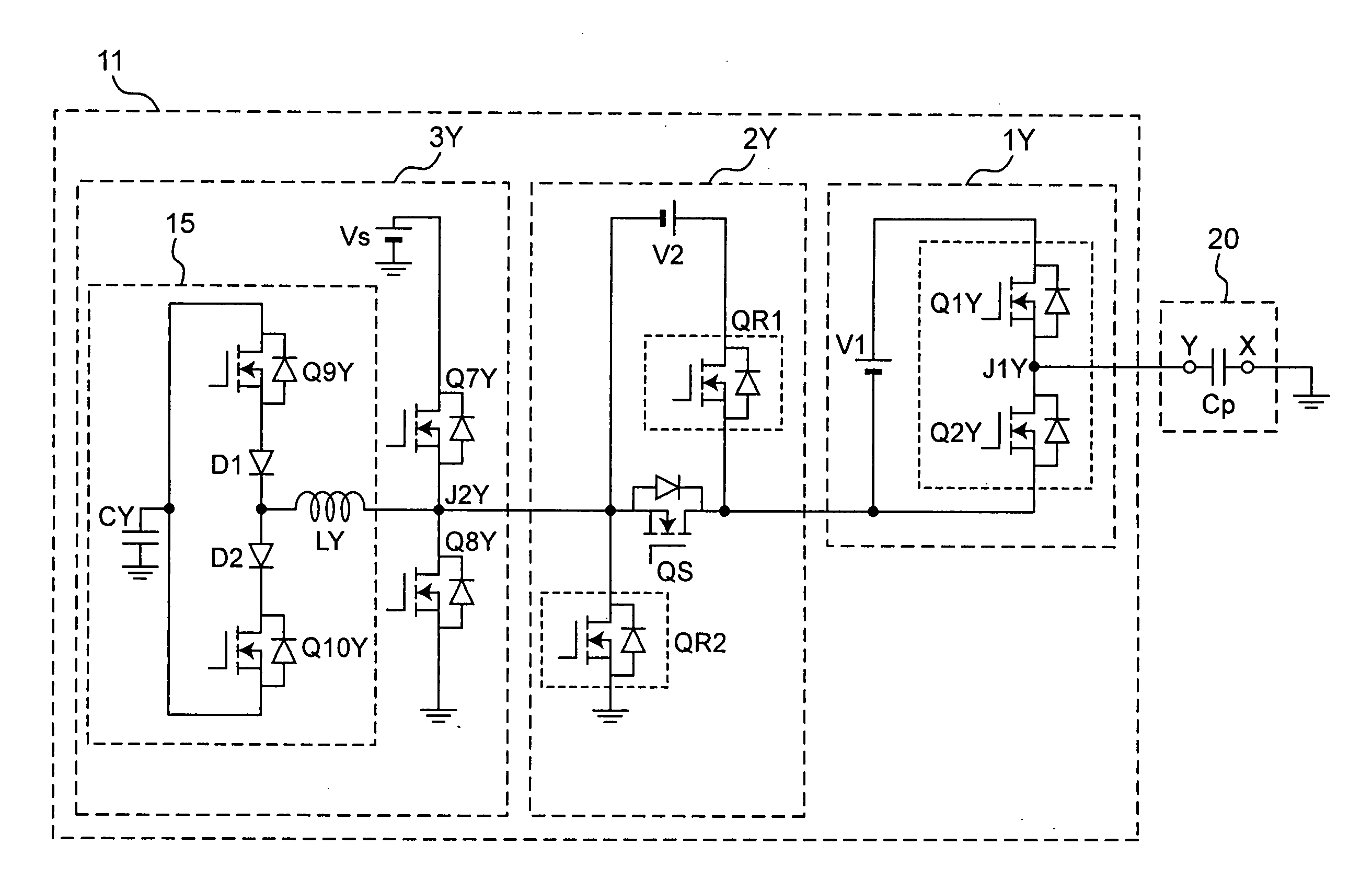
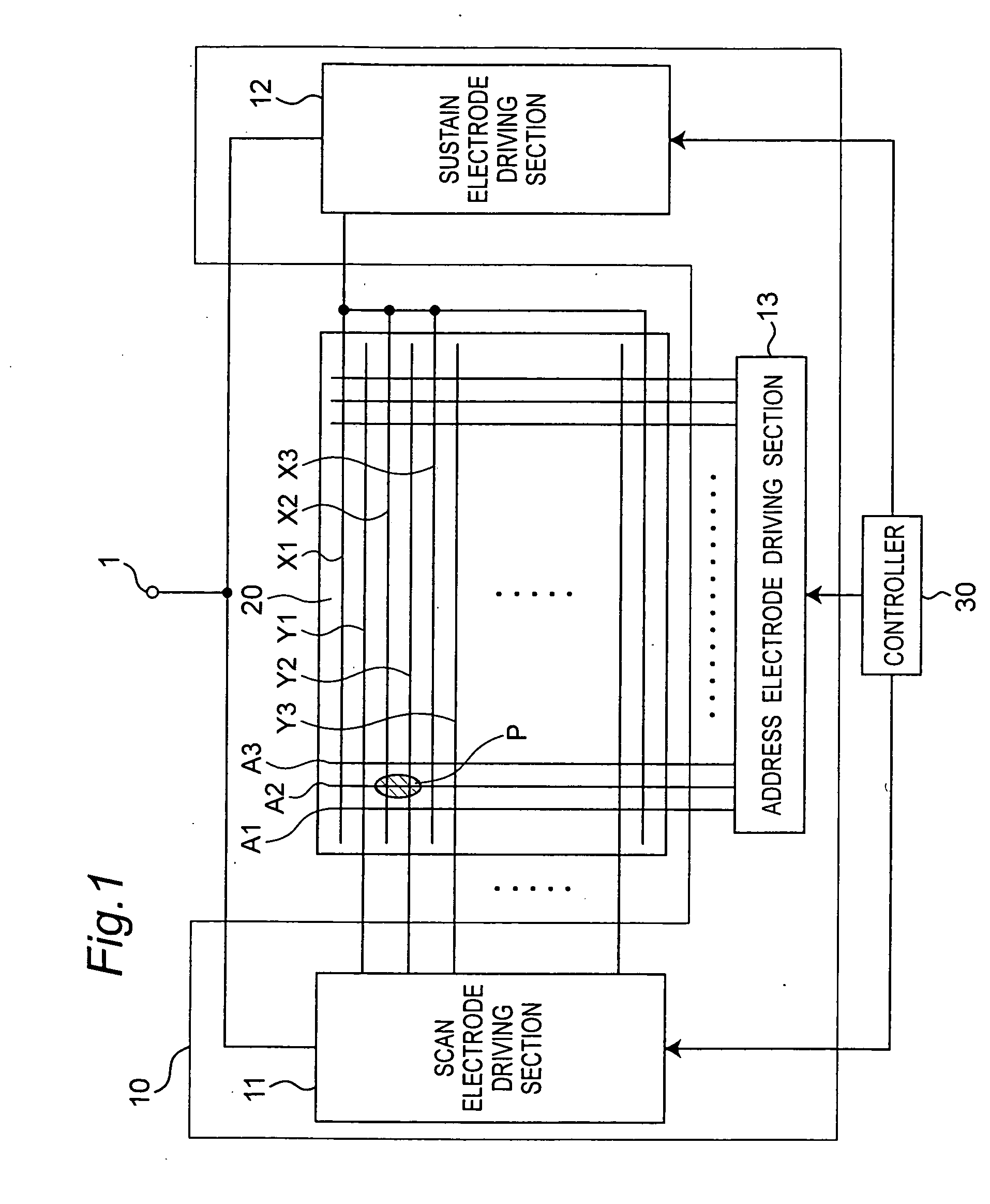
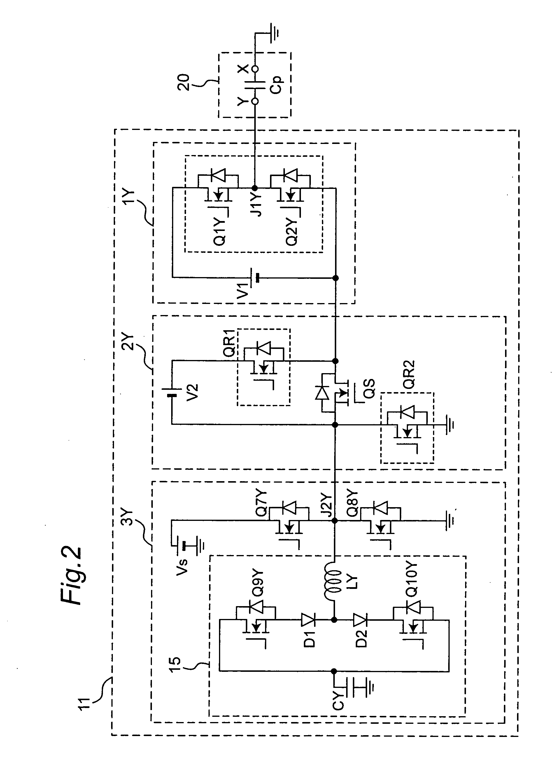
[0034]FIG. 1 is a block diagram showing a configuration of a plasma display in an embodiment of the invention. The plasma display includes a PDP driving apparatus 10, a plasma display panel (PDP) 20, and a controller 30.

(Plasma Display Panel)

[0035] The PDP 20 is, for example, of AC type, having three-electrode surface discharge type structure. On a back surface of the PDP 20, address electrodes A1, A2, A3, . . . are disposed along the width direction of the panel. On a front surface of the PDP 20, sustain electrodes X1, X2, X3, . . . and scan electrodes Y1, Y2, Y3, . . . are disposed alternately along the longitudinal direction of the panel. The sustain electrodes X1, X2, X3, . . . are mutually coupled to have substantially equal potential. The address electrodes A1, A2, A3, . . . , and scan electrodes Y1, Y2, Y3, . . . can be controlled individually for the potential.

[0036] A discharge cell is disposed at an intersection (for example, sh...

embodiment 2

[0113] The plasma display in embodiment 2 of the invention has exactly the same configuration as the plasma display (FIG. 1) in embodiment 1. Hence, the detail of the configuration is same as explained in embodiment 1.

[0114]FIG. 6 shows an equivalent circuit diagram of the scan electrode driving section 11 and the PDP 20 in embodiment 2. The scan electrode driving section 11 of this embodiment is different from that of embodiment 1 (see FIG. 2) in that the high side sustain switch element Q7Y is a normally-on switch element and the low side sustain switch element Q8Y is a normally-off switch element. Other constituent elements of the embodiment are same as those in embodiment 1, and hence the explanation is omitted.

[0115] The equivalent circuit of the PDP 20 is, same as in FIG. 2, expressed only as a panel capacity Cp of the PDP 20, and the path of current flowing in the PDP 20 during the discharge in the discharge cell is omitted. Also the sustain electrode driving section connec...

embodiment 3

[0136] Embodiment 3 of the invention shows other configuration of the power source circuit.

[0137]FIG. 8 shows a configuration of the power source circuit in this embodiment. The power source circuit in the embodiment is different from that in embodiment 1 in including a second cut off switch element QS2 and a short switch element QS3. Other constituent elements in the embodiment are same as constituent elements in embodiment 1.

[0138] As shown in FIG. 8, the power source circuit includes a power factor correction circuit 30, a first DC-DC DC converter 31, a second DC-DC converter 32, a first input capacitor C1, a second input capacitor C2, a first cut off switch QS1, an alternating-current (AC) power detector 35, a second cut off switch element QS2, and a short switch element QS3.

[0139] One end of the second cut off switch element QS2 is connected to the positive pole of the second gate voltage VG2, and the other end is connected to the second power output terminal 34. One end of ...


PUM


Abstract

A PDP driving apparatus drives a plasma display panel (PDP) having sustain electrodes, scan electrodes, and address electrodes. The PDP driving apparatus has a plurality of switch elements. At least one of the plurality of switch elements is a normally-on switch element which turns on while a driving voltage is not applied to itself.

Description

BACKGROUND OF THE INVENTION [0001] 1. Field of the Invention [0002] The invention relates to a driving apparatus of a plasma display panel. [0003] 2. Related Art [0004] Plasma display is a display device making use of light emitting phenomenon by gas discharge. The display portion of the plasma display, that is, a plasma display panel (hereinafter called PDP) is more advantageous than other display devices in the aspect of large screen, thin panel, and wide viewing angle. PDP is roughly classified into DC type operated by direct-current pulses, and AC type operated by alternating-current pulses. The AC type PDP is particularly high in luminance, and simple in structure. Therefore, the AC type PDP is suited to mass production and finer pixel size, and is used in a wide range. [0005] An AC type PDP has, for example, a three-electrode surface discharge structure (see, for example JP2003-15600, A). In this structure, address electrodes are disposed on a back surface of PDP in longitudin...

Claims


Application Information

Patent Timeline
IPC IPC(8): G09G3/28
CPCG09G3/296G09G2330/04G09G2330/027G09G3/2965
Inventor INOUE, MANABU
Owner PANASONIC CORP
Why Eureka
Try Eureka