Cable management bar

Inactive Publication Date: 2007-08-16
BELDEN TECHNOLOGY INC
View PDF18 Cites 24 Cited by
  • Summary
  • Abstract
  • Description
  • Claims
  • Application Information

AI Technical Summary

Benefits of technology

[0005] In order to address the above and other drawbacks, there is disclosed a cable management bar for attachment in front of an elongate panel mounted on a rack comprising a pair of vertical rails spaced at a predetermined distance from each other and bordering a surface, the panel comprising a face comprising a plurality of cable terminating elements therein, each of the elements terminating one of a plurality of cables. T

Problems solved by technology

These environments are limited in space and there are a limited number of racks that can be installed in these confined environments.
As such, the in-rack space is also limi

Method used


Image

  • Cable management bar
  • Cable management bar
  • Cable management bar

Examples


Embodiment Construction

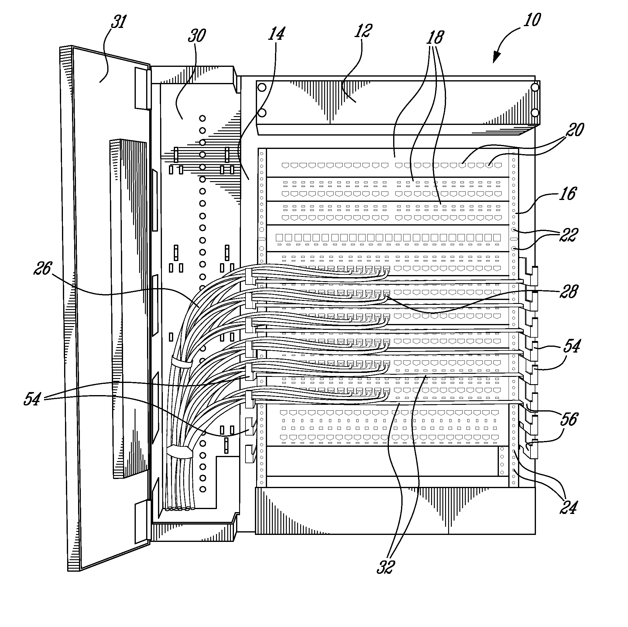
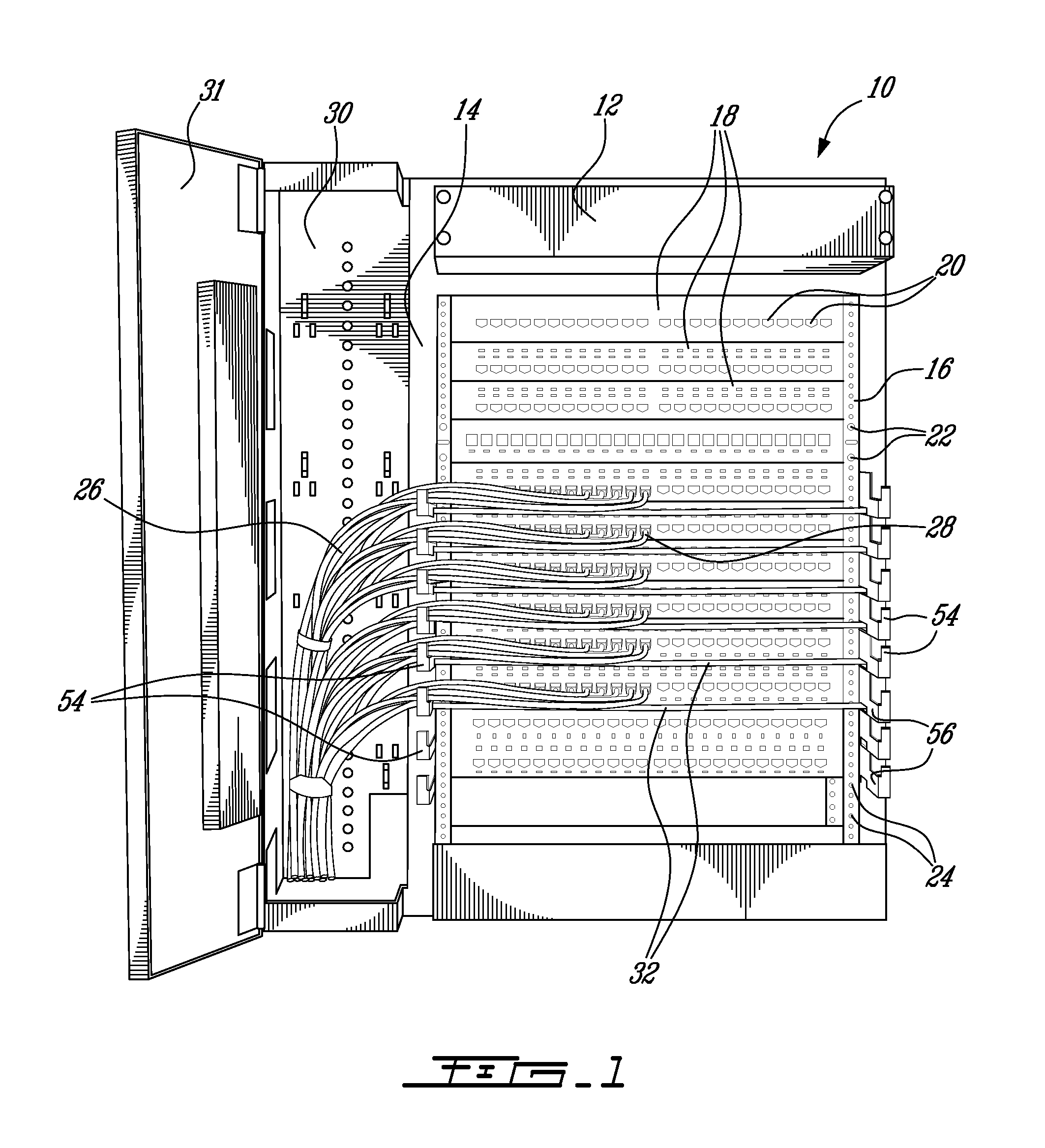
[0021] Referring now to FIG. 1, a cable management rack, generally referred to using the reference numeral 10, will now be described. The cable management rack 10 is comprised of a frame 12 comprised two vertical rails 14, 16 onto which a plurality of patch panels or other networking equipment as in 18 can be mounted. As known in the art, such patch panels as in 18 typically comprise a number of sockets (or modules) as in 20 and are independently mounted to the rack 10 by mounting hardware such as bolts as in 22 which mate with corresponding threaded holes as in 24 machined at intervals into the two vertical rails 14, 16. The sockets as in 20 are typically adapted to receive a cable as in 26 which is terminated by a standardised plug as in 28 such plugs conforming to the ubiquitous RJ-45 standard (although other technologies such as co-axial or those terminating fiber optic cables such as LC, SC or the like may also be terminated at such a rack).

[0022] Still referring to FIG. 1, th...


PUM


Abstract

A cable management bar is disclosed for attachment in front of a panel for supporting a plurality of cables, typically telecommunication cables, which are terminated at a plurality of sockets in the panel. The bar comprises an elongate cable supporting portion and at least one mounting bracket for securing the cable supporting portion. Cable management bar can be hinged relative to the front face of the panel such that it can be moved between a cable supporting position and a panel accessing position. There is also disclosed a cable guide for guiding the cables as they pass over (or under) the cable management bar.

Description

CROSS REFERENCE TO OTHER APPLICATIONS [0001] This application claims priority on U.S. Provisional Application No. 60 / 760,387, filed on Jan. 20, 2006 which is herein incorporated by reference in its entirety.FIELD OF THE INVENTION [0002] The present invention relates to a cable management bar. In particular the present invention relates to a cable management bar for supporting cables being terminated at equipment such as distribution panels and patch bays or the like typically supported in a cable management rack. BACKGROUND TO THE INVENTION [0003] In the networking environment, racks are used to install active equipment (switches, servers, etc), cross connecting equipment (patch panels, mini racks, cable management, etc) and other required equipment. Such racks are installed in main telecom rooms, telecom closets and in data centre environments. These environments are limited in space and there are a limited number of racks that can be installed in these confined environments. As su...

Claims


Application Information

Patent Timeline
IPC IPC(8): H01R29/00
CPCH01R9/2416H04Q1/06H04Q1/13H04Q1/021H04Q1/09H05K7/186
Inventor SAMPSON, RODERICKTURNER, SIDNEY E.
Owner BELDEN TECHNOLOGY INC
Why Eureka
Try Eureka