Multipurpose optical fibre drop cable

a drop cable and optical fibre technology, applied in the field of optical fibre cables, can solve the problems of affecting all the components of the cable, straining the drop cable, and external mounting drop cables are subject to additional variable loading, etc., and achieve the effect of increasing tensile performance and improving tensile performan

Active Publication Date: 2014-08-28
PRYSMIAN TELECOM CABLES & SYST UK +1
View PDF6 Cites 22 Cited by
  • Summary
  • Abstract
  • Description
  • Claims
  • Application Information

AI Technical Summary

Benefits of technology

[0022]In a preferred embodiment, at least one optical fibre unit is stranded with at least one stranding element. The stranding can be either SZ or helical. The stranding configuration provides the cable with a positive excess of optical fibre length. A positive excess of optical fibre length can help and relief the optical fibre strain stress.
[0055]Both in case of co-extrusion and of extrusion of one layer immediately after the other, the temperature difference between extruded inner sheath and outer sheath material to be extruded shall be selected by the skilled person in view of the kind of materials used for outer and inner sheath. If the temperature difference is too great the materials will thermally fuse together, at least partially, thereby increasing the peeling force, while if it is too small then there would be little or no adhesion between the inner and outer sheaths and this could introduce a ‘slip layer’ between the inner and outer sheaths thus limiting the strain resistance of the cable.

Problems solved by technology

In addition, externally mounted drop cables are subject to additional variable loading due to wind force and settling of moisture or ice formation.
This additional loading results in strain in the drop cable and will affect all the components of the cable including the data carrying components.
If the radial thickness of the cable sheath over the strength member is too thin then the sheath material will fracture, but if the said thickness is too high then the amount of load being transferred to the strength member is reduced, as the cable sheath acts as a buffer and sheath shear and possibly break or slippage may occur.
Both these solutions are expensive.
A cable having low fire hazard sheathing is not suitable for outdoor use where resistance to environmental (both mechanical and chemical) stresses is required, which may not sufficiently provided by the low fire hazard sheathing.
In addition, an indoor cable can suffer from temperature fluctuations, in particular from shrinkage at low temperatures after deployment.
Whilst aramid yarns as strength members are well proven, there may be a problem in using them when there is a defined maximum tensile strength requested for the cable.
The load at which aramid yarns ultimately breaks is not as well defined as for metal or grp (glass reinforced polymer) strength members, but rather lays in a range which may provide uncertainty in the application, unless the size is increased, resulting in very high costs.
In addition, aramid yarns would not provide resistance to axial compression, e.g. due to thermal shrinkage.
The Applicants faced the problem of providing a drop telecommunication cable suitable both for outdoor and to indoor use.
In particular, the Applicants faced the problem of providing a cable with suitable strain and environmental resistance when used outdoor, and of retaining a sufficient strain resistance and fire performances when used indoor.
Strength members location close to the outer cable surface was believed to be required for transferring the load from the securing device to the strength members, but if said strength members are embedded in the outer sheath, made of a material suitable for outdoor application but not fire resistant, they get lost with the removal of the outer sheath at the moment of the indoor deployment.
However the coexistence of live aerial electric conductors can cause electric voltage arcing across the metallic strength members.
If the temperature difference is too great the materials will thermally fuse together, at least partially, thereby increasing the peeling force, while if it is too small then there would be little or no adhesion between the inner and outer sheaths and this could introduce a ‘slip layer’ between the inner and outer sheaths thus limiting the strain resistance of the cable.

Method used


Image

  • Multipurpose optical fibre drop cable
  • Multipurpose optical fibre drop cable
  • Multipurpose optical fibre drop cable

Examples


Embodiment Construction

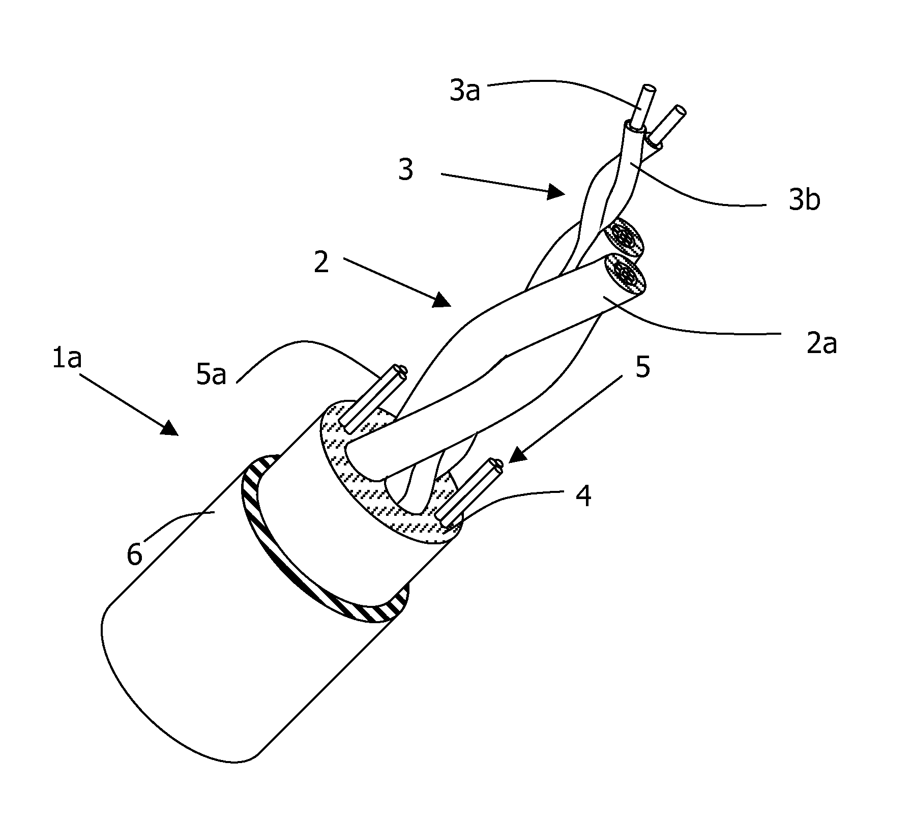
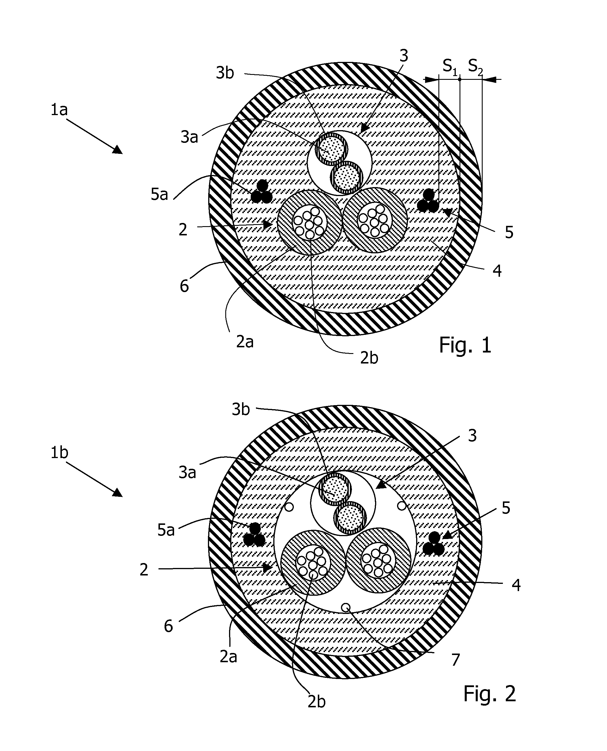
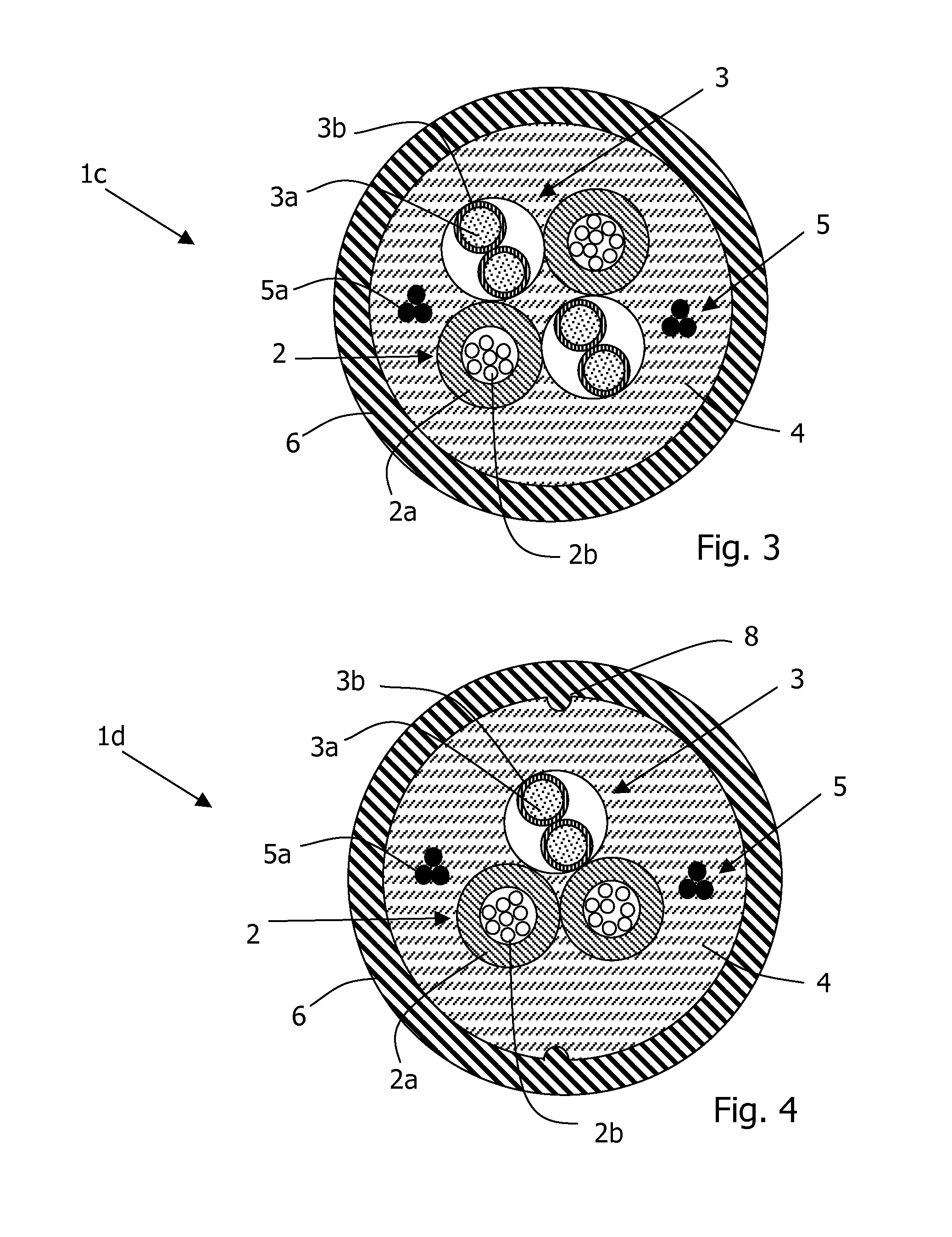
[0064]FIG. 1 shows a cable is according to the present disclosure. Cable 1a includes two optical fibre units 2 each comprising a tube 2a housing a number of optical fibre 2b (generally twelve, though the drawing shows eight only).

[0065]Typically the optical fibres 2b are loosely housed within the tube 2a, so that substantially no mechanical coupling is there between fibres 2b and tube 2a, thereby preventing a load applied to the tube from being transmitted to the fibres.

[0066]The optical fibre unit 2 is stranded with a stranding element that, in the depicted case, is a twisted pair 3 of insulated electric conductors, each comprising a copper conductor 3a surrounded by an insulating layer 3b. The insulating layer 3b can be made, for example, of a mixture of propylene homopolymer or copolymer and ethylene copolymer comprising an inorganic filler, for example aluminium or magnesium hydroxide, as described, for example, in EP 0 893 801, EP 0 893 802 or WO 99 / 05688.

[0067]Optical fibre un...


PUM

PropertyMeasurementUnit
temperatureaaaaaaaaaa
angleaaaaaaaaaa
radial stripping forceaaaaaaaaaa

Abstract

A telecommunication cable includes at least one optical fibre unit surrounded by a low fire hazard halogen free polymeric inner sheath that is covered by and in contact with a peelable, environmentally resistant polymer outer sheath. At least two discrete strength members are embedded into the low fire hazard halogen free polymeric inner sheath. The cable is intended for outdoor and indoor use.

Description

BACKGROUND OF THE INVENTION[0001]The present invention relates to an optical fibre cable for telecommunication, in particular to a drop optical fibre cable suitably deployed both outdoor and indoor.[0002]As “drop cable” it is meant an optical cable operating as the last link of an access distribution network, typically serving just one subscriber.[0003]Optical fibre telecommunication cables for outdoor use should have mechanical characteristics such to withstand environmentally challenging situation. For example, as reported by GB2368404, aerial (or overhead) telecommunication drop cables are suspended from poles in a catenary and sag due to their own weight. The extent of the sag on installation is determined by the tension in the drop cable and is designed to be within a range of values determined by the acceptable drop cable tension and the acceptable extent of eventual sag to avoid hazard. In addition, externally mounted drop cables are subject to additional variable loading due...

Claims


Application Information

Patent Timeline
Patent Type & Authority Applications(United States)
IPC IPC(8): G02B6/44B29D11/00
CPCG02B6/443B29D11/00701G02B6/4416G02B6/4433G02B6/4436Y10T29/49817
Inventor SUTEHALL, RALPHDAVIES, MARTINLANG, IAN DEWIBONICEL, JEAN-PIERRE
Owner PRYSMIAN TELECOM CABLES & SYST UK
Why Eureka
Try Eureka