High Performance Telecommunications Cable

a high-performance, telecommunications cable technology, applied in the direction of cables with twisted pairs/quads, etc., can solve the problems of twisted pair conductors and electromagnetic interference between twisted pair conductors, and achieve the effect of reducing cross talk

Active Publication Date: 2008-07-10
BELDEN CANADA ULC
View PDF25 Cites 27 Cited by
  • Summary
  • Abstract
  • Description
  • Claims
  • Application Information

AI Technical Summary

Benefits of technology

[0023]Furthermore, there is disclosed a method for reducing cross talk between adjacent cables in a telecommunications system, the method comprising the steps of, for each of the cables, providing a plurality of twisted pairs of conductors, winding an elongate filler element around the twisted pairs and covering the twisted pairs and the element with a cable jacket, the element introducing a visible distortion into an outer surface of the jacket.

Problems solved by technology

A major technical difficulty in such installations is the electromagnetic interference between the twisted pair conductors of a “victim” cable and the twisted pair conductors of other cables in the vicinity of the victim cable (the “offending” cables).
More particularly, active systems at receiving and emitting ends of 10 G Local Area Networks are able to cancel internal Cross Talk (or NEXT) but cannot do the same with ANEXT.

Method used


Image

  • High Performance Telecommunications Cable
  • High Performance Telecommunications Cable
  • High Performance Telecommunications Cable

Examples


Embodiment Construction

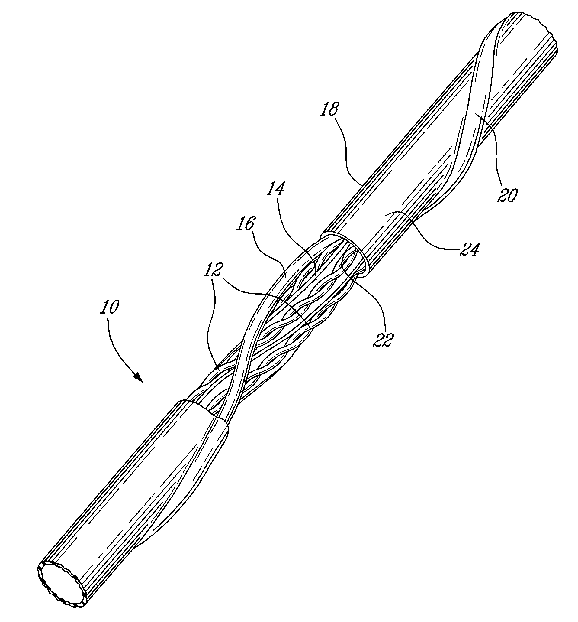
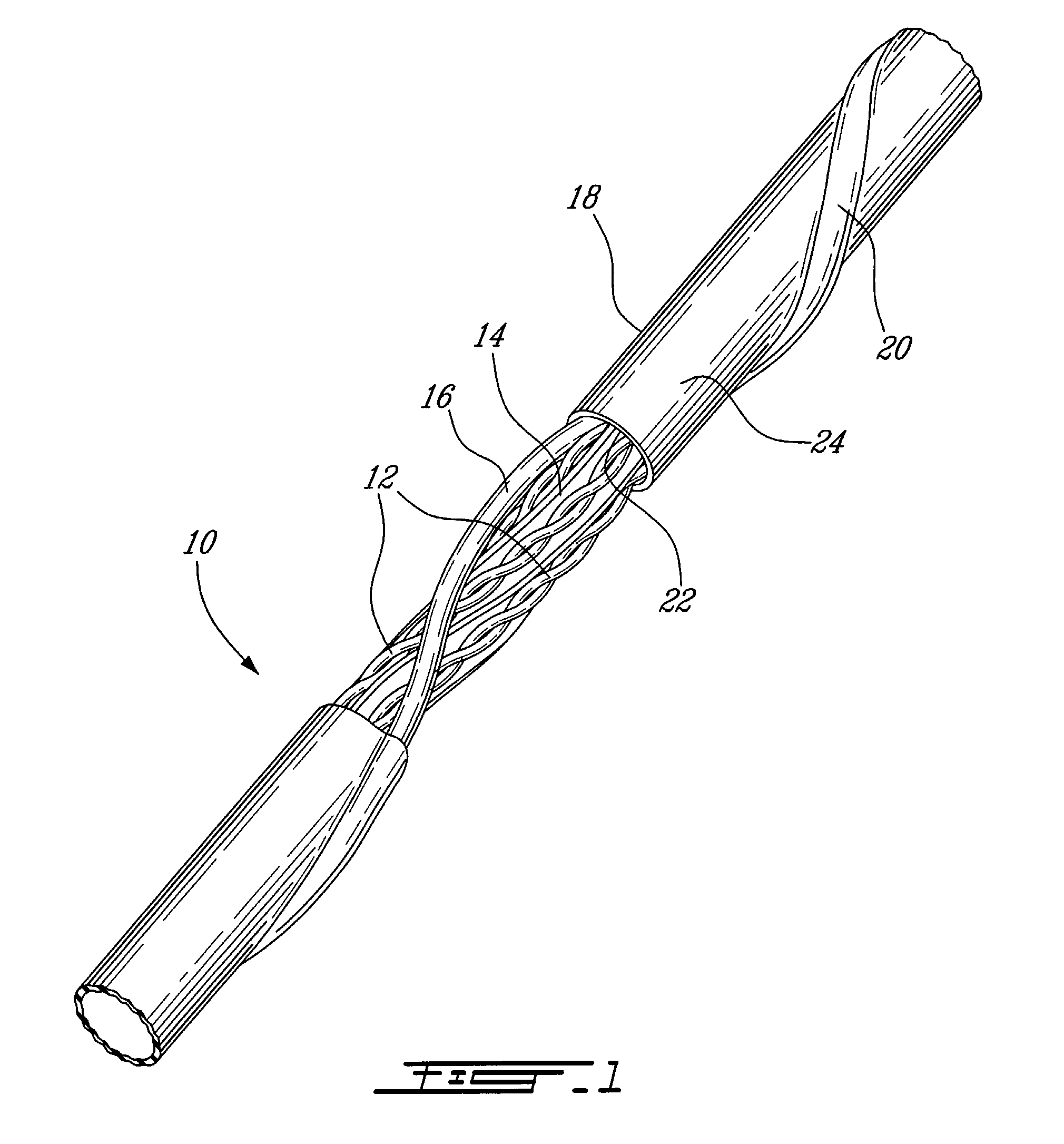
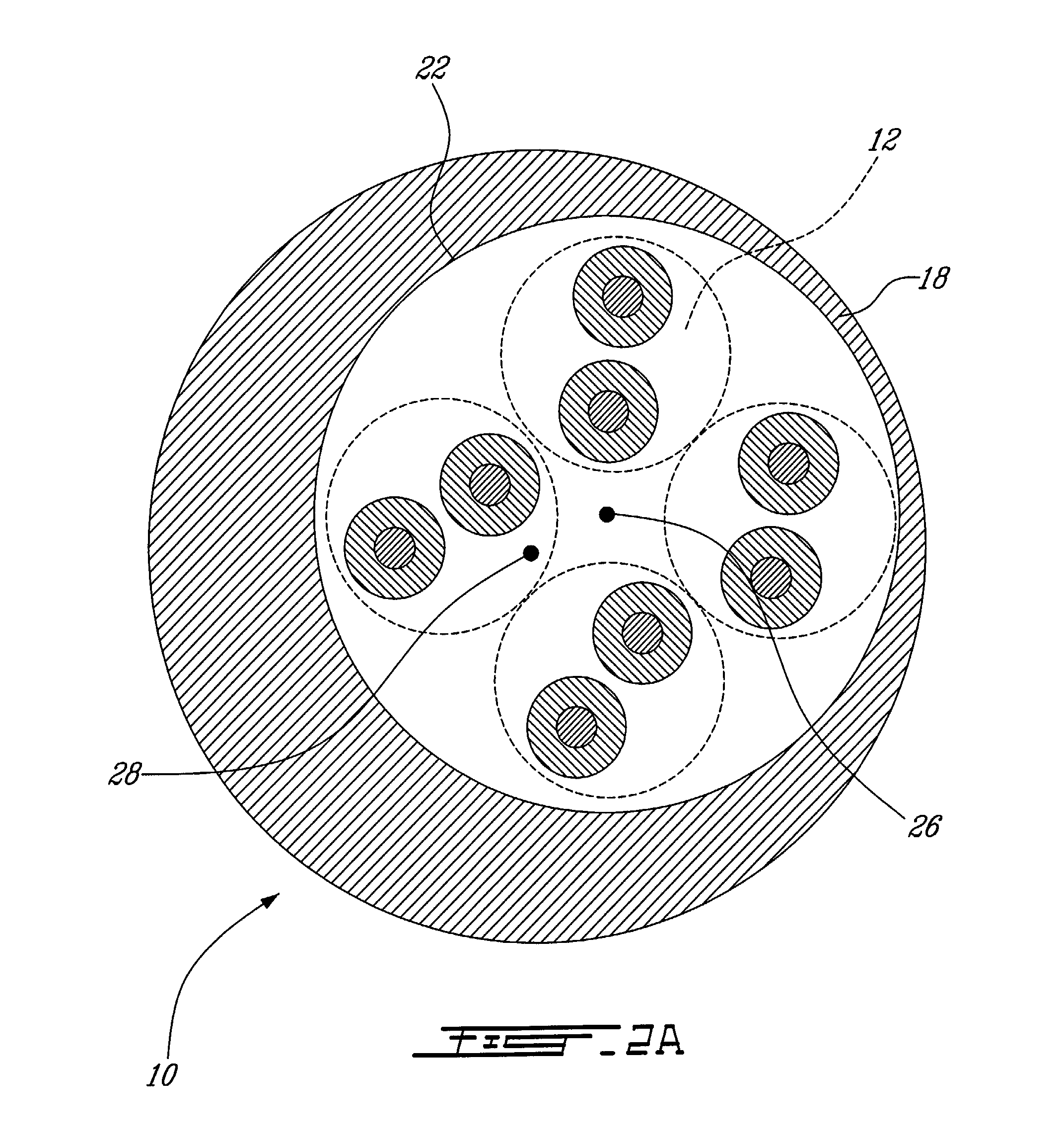
[0033]Referring now to FIG. 1, a telecommunications cable, generally referred to using the reference numeral 10 will now be described. The cable 10 is comprised of four twisted pairs of conductors as in 12. Each twisted pair 12 is twisted with a constant or variable or random twist lay, and the twist lay of different pairs of conductors is typically different. A separator spline 14 is provided for maintaining a spacing between the four twisted pairs of conductors as in 12. As known in the art, the spline 14 is typically manufactured from a non-conductive material such as pliable plastic or the like. The twisted pairs as in 12 as well as the spline 14 are in turn illustratively stranded together such that as one moves along the cable 10 the twisted pairs as in 12 and the spline 14 rotate helically around an axis located along the centre of the cable 10. In this regard, the strand lay of the twisted pairs as in 12 and the spline 14 may be constant or variable or random.

[0034]Still ref...


PUM

PropertyMeasurementUnit
oblique angleaaaaaaaaaa
angleaaaaaaaaaa
angleaaaaaaaaaa

Abstract

A telecommunications cable comprising four twisted pairs of conductors and a separator spline comprised of a principal dividing strip and a first subsidiary dividing strip attached longitudinally along a first side of the principal dividing strip and a second dividing strip attached longitudinally along a second side of the principal dividing strip, the spline separating the four twisted pairs such that they are arranged in a staggered configuration. A telecommunications cable comprising a first set of two twisted pairs of, conductors arranged on opposite sides of and running along an axis and separated by a first distance and a second set of two twisted pairs of conductors on opposite sides of and running along the axis and separated by a second distance less than the first distance. Each of the first set of twisted pairs has a twist lay which is shorter than a twist lay of either of the second set of twisted pairs. A telecommunications cable comprising a plurality of twisted pairs of conductors arranged around and running along an axis, and a cable jacket surrounding the twisted pairs, the jacket comprising an outer surface. The outer surface defines a tube having a helical centre path arranged around and running along the axis. A method for reducing cross talk between adjacent cables in a telecommunications system, the method comprising the steps of, for each of the cables, providing a plurality of twisted pairs of conductors, winding an elongate filler element around the twisted pairs and covering the twisted pairs and the element with a cable jacket, the element introducing a visible distortion into an outer surface of the jacket.

Description

FIELD OF THE INVENTION[0001]The present invention relates to a high performance telecommunications cable. In particular, the present invention relates to a cable designs designed to reduce PSANEXT.BACKGROUND OF THE INVENTION[0002]The introduction of a new IEEE proposal for 10 G (Gigabit per second) transmission speeds over copper cable has spearheaded the development of new copper Unshielded Twisted Pair (UTP) cable designs capable to perform at this speed.[0003]As known in the art, such UTP cables typically consist of four twisted pairs of conductors each having a different twist lay. Additionally, in many installations, a number of UTP cables are arranged in cable runs such that they run side by side and generally in parallel. In particular, in order to simplify the installation of UTP cables in cable runs, EMC conduit, patch bays or the like, a number of UTP cables are often bound together using ribbon, twist ties, tape or the like. A major technical difficulty in such installati...

Claims


Application Information

Patent Timeline
Patent Type & Authority Applications(United States)
IPC IPC(8): H01B11/04H01B11/02
CPCH01B11/06
Inventor VEXLER, GAVRIELBOHBOT, MICHELDION, YVESHUMPHREY, ERICRICHARD, MICHEL
Owner BELDEN CANADA ULC
Why Eureka
Try Eureka