Reduced crosstalk sensor and method of formation

Active Publication Date: 2005-08-25
MICRON TECH INC
38 Cites 110 Cited by

AI-Extracted Technical Summary

Problems solved by technology

Adjacent pixel cells 100a, 100b, and/or other pixel cells (not shown) of array 199, can interfere with each another causing crosstalk, which results in p...

Benefits of technology

[0011] The invention provided a deep trench isolation structure and method for reducing crosstalk among semiconductor circuits, and particularly among adjacent photodiodes formed in pixel circuits. Under a preferred embodiment, a trench is etched into a substrate adjacent to a photodiode region, wh...

Abstract

Isolation methods and devices for isolating regions of a semiconductor device are disclosed. The isolation methods and structures include forming an isolating trench among pixels or other active areas of a semiconductor device. The trench extends through the substrate to the base layer, wherein a liner may be deposited on the side walls of the trench. A conductive material is deposited into the trench to block electrons from passing through.

Application Domain

Technology Topic

Image

  • Reduced crosstalk sensor and method of formation
  • Reduced crosstalk sensor and method of formation
  • Reduced crosstalk sensor and method of formation

Examples

  • Experimental program(1)

Example

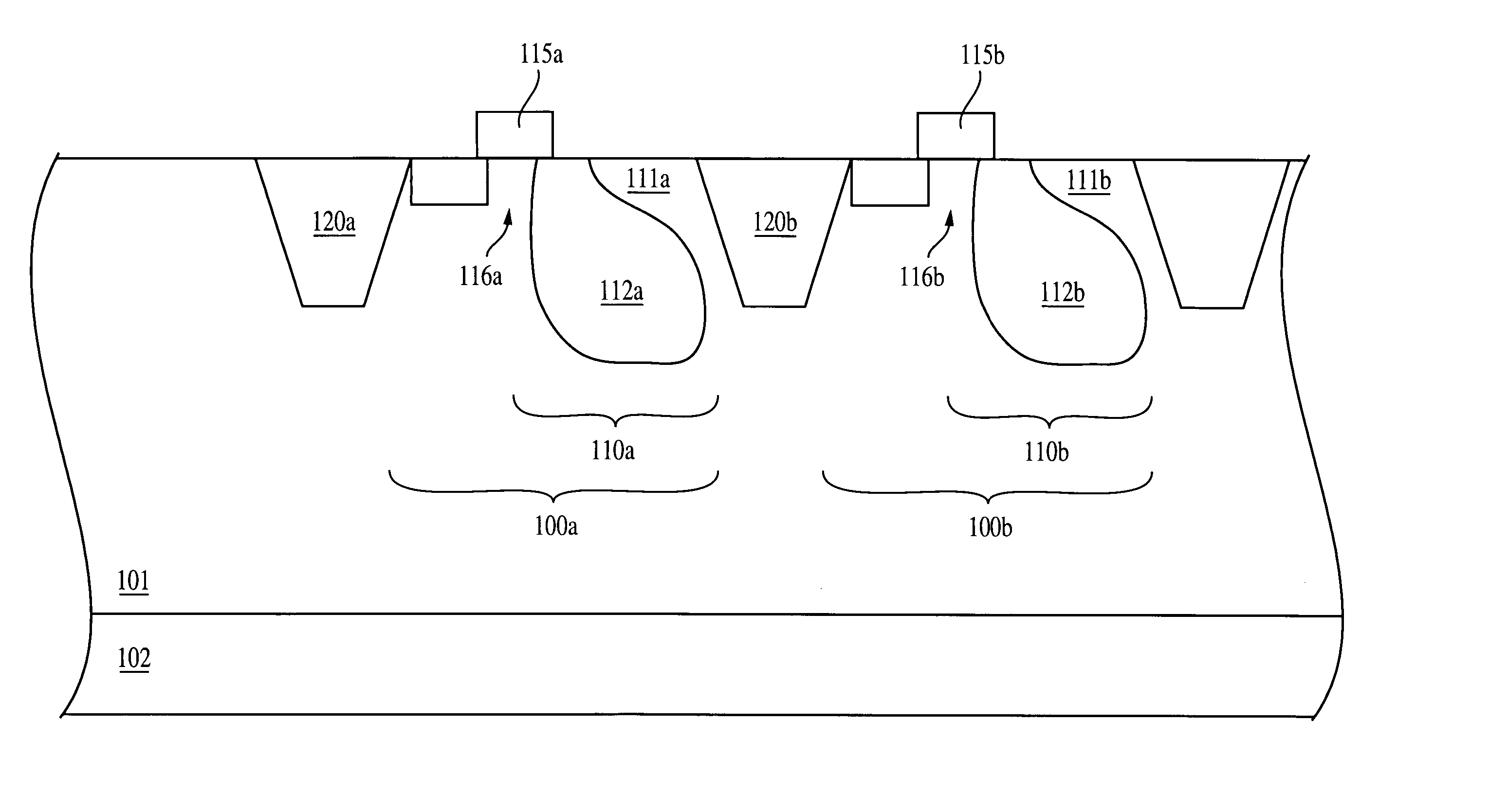
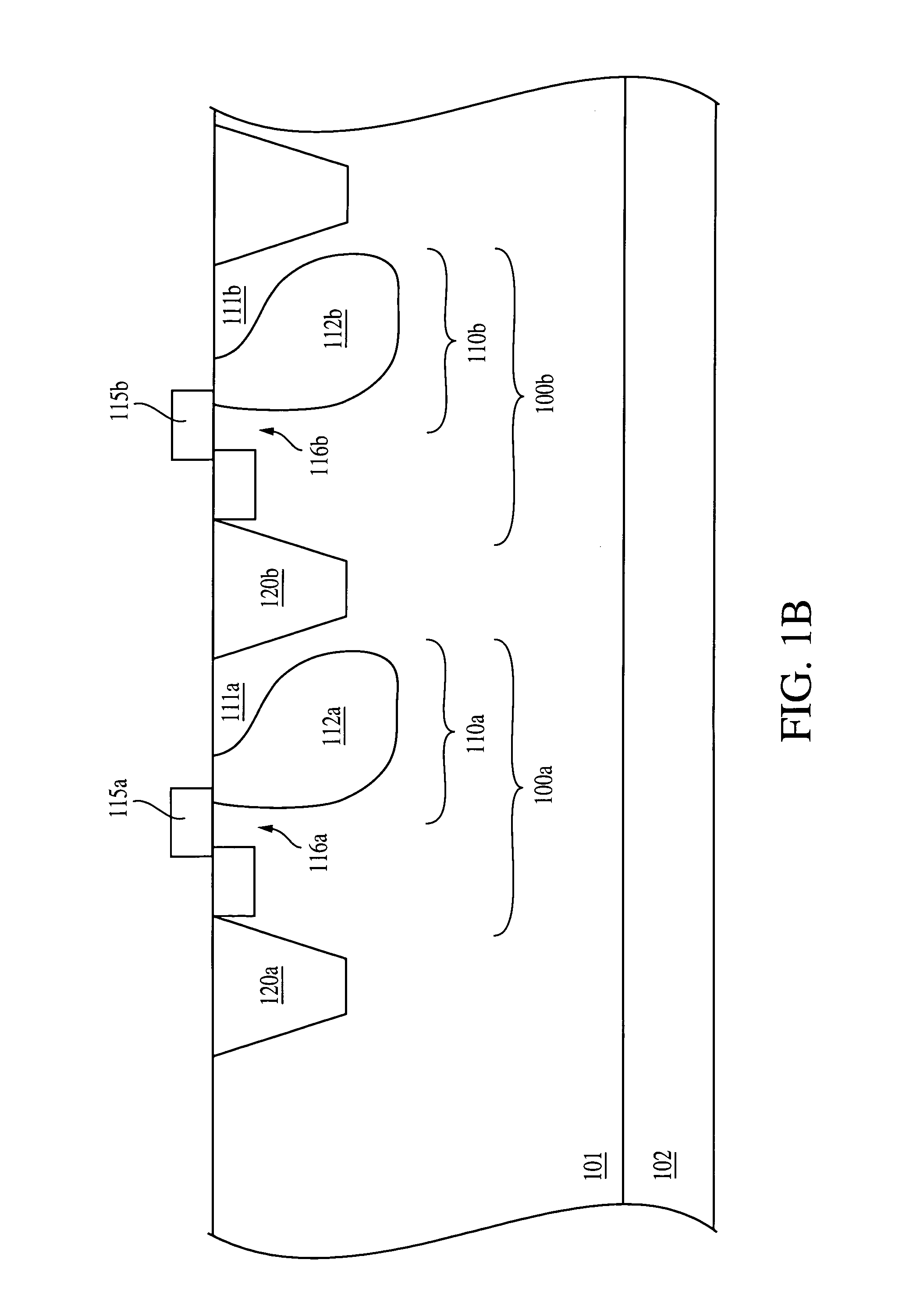
[0024] In the following detailed description, reference is made to the accompanying drawings, which form a part hereof, and in which is shown by way, of illustration of specific embodiments in which the invention may be practiced. These embodiments are described in sufficient detail to enable those skilled in the art to practice the invention, and it is to be understood that other embodiments may be utilized, and that structural, logical and electrical changes may be made without departing from the spirit and scope of the present invention.
[0025] The terms “wafer” and “substrate” are to be understood as including silicon, silicon-on-insulator (SOI), or silicon-on-sapphire (SOS) technology, doped and undoped semiconductors, epitaxial layers of silicon supported by a base semiconductor foundation, and other semiconductor structures. Furthermore, when reference is made to a “wafer” or “substrate” in the following description, previous process steps may have been utilized to form regions or junctions in the base semiconductor structure or foundation. In addition, the semiconductor need not be silicon-based, but could be based on silicon-germanium, germanium, or gallium-arsenide.
[0026] The term “pixel” refers to a picture element unit cell having an active area and containing a photo-conversion device and other devices, e.g., transistors, for converting electromagnetic radiation to an electrical signal. For purposes of illustration, a representative pixel cells are illustrated in the Figure s and description herein, and typically fabrication of all pixels in an image sensor will proceed simultaneously in a similar fashion.
[0027] For simplicity, exemplary embodiments described herein are explained with reference to a CMOS image sensor. However, it should be noted that the invention is not limited to CMOS image sensors and may be used in any suitable device, for example, a charge coupled device (CCD) image sensor.
[0028] Shallow trench isolation regions for CMOS image sensors generally have a depth of less than about 3000 Angstroms (Å) and are generally around about 2000 Å to about 2500 Å. Typically, STI regions are filled with a conventional insulator, such as oxides or high density plasma (HDP) oxides. However, it is difficult to fill trenches having a depth greater than 2500 Å with conventional insulators due to the limited spacing within the trench, for example, undesirable voids or air gaps are formed when oxides are used to fill trenches having a depth greater than about 2500 Å. The width (W) may vary, but is preferably shorter than the depth (D) of the trench.
[0029] In accordance with an exemplary embodiment of the invention shown in FIG. 2, a trench 202 is preferably filled with conductive materials containing silicon, preferably polysilicon or silicon-germanium. Conductive materials containing silicon may be easily deposited into trenches of various depths, unlike conventional insulation materials, e.g., silicon dioxide, silicon nitride, NO, ON, HDP, and ONO, which are difficult to fill in deep trenches. Thus, using a conductive material containing silicon, or a combination of such conductive materials containing silicon, to fill the trench 202 allows easy formation of a trench, particularly, a deep trench having a depth (D) greater than about 2000 Å, and preferably about 4000 to about 5000 Å. In a preferred embodiment, the trench 202 should extend to the epi layer 201 as shown in FIG. 2
[0030] Generally, the deeper the trench 202 the better the isolation. With respect to CMOS image sensors in particular, the deeper the trench 202 the higher the electron storage capacitance of the CMOS image sensor. A trench according to the invention is deeper than a shallow trench, and accordingly has longer sidewalls than a shallow trench. Therefore, the longer sidewalls allow for a larger electrical connection region 323 along the sidewalls of the trench 202 such that electron storage capacitance, e.g., hole accumulation, in the electrical connection region 323 is increased in accordance with the invention.
[0031] The use of a trench in accordance with the invention provides improved isolation between pixels. The deeper trench better inhibits electrons from diffusing under the isolation trench to an adjacent pixel thereby preventing crosstalk between neighboring pixels. Also the deeper trench allows for tighter isolation design rules. Deeper trenches may also be narrower than shallow trenches, while still providing effective isolation between neighboring regions. Accordingly, the source/drain regions of one pixel may be brought closer to the active layer of an adjacent pixel, by narrowing the width of the deep trench.
[0032] The fabrication of an exemplary trench 202 is described below with reference to FIGS. 3A-3C. No particular order is required for any of the steps described herein, except for those logically requiring the results of prior actions. Accordingly, while the steps below are described as being performed in a general order, the order is exemplary only and may be altered.
[0033] As shown in FIG. 3A, a trench 202 is etched into substrate 200, which is adjacent to photodiode region 203. The trench 202 preferably extends near, or directly above base layer 201. An anisotropic etch is performed into the silicon substrate 200 to create a deep trench 202. A resist and mask are applied, and photolithographic techniques are used to define the area to be etched-out of substrate 200. A directional etching process, such as Reactive Ion Etching (RIE), or etching with a preferential anisotropic etchant is used to etch into a doped active layer to form the trench 202. The resist and mask are removed leaving a structure that appears as shown in FIG. 3A.
[0034] Referring now to FIG. 3B, an oxide, i.e., silicon oxide, silicon dioxide or other dielectric liner 204, is grown or deposited on sidewalls 210 and bottom 220 of trench 202. The liner may be formed by known techniques and may be a high density plasma (HDP) oxide, a spin on dielectric (SOD), e.g., silicon oxide, or other suitable material. Liner 204 can be substantially conformal such that the thickness of the liner 204 is substantially the same along the sidewalls 210 and at the bottom 220 of the trench 202. In general, the thickness of the dielectric liner 204 along the sidewalls 210 should be at least about 100 Angstroms. Alternatively, a direct deposit of an insulator could be performed.
[0035] Furthermore, part of the trench may be filled with disposable, doped oxide material after the trench etch to create a film over the trench. The disposable oxide film may be boron-doped BSG, or phosphor-doped PSG, or other suitable material. After the film is deposited in the trench, a HF dip will remove part of the film from the top of the trench, leaving film only along the sidewalls and bottom of the trench. A short anneal process then follows to out-diffuse dopants from the film to the sidewalls of the trench. In this manner, the boron-doped BSG acts as a solid-source diffusion source for boron.
[0036] In the case of a PNP photodiode having a BSG film, a high concentration boron doped region will be formed near the sidewall and the bottom of the trench. This high-doped region will serve to connect the top surface p-layer 203 to the bottom p-substrate epi layer 201 in a pinned photodiode structure. Also, high conical sidewalls without the use of high dose implants can create a good interface without defects for reduced dark current.
[0037] Referring now to FIG. 3C, a highly doped (in-situ doped) n-type or p-type conductive material containing silicon 205 is deposited to fill the trench 202. Suitable conductive materials containing silicon include polysilicon and silicon-germanium. Alternatively, the trench 202 may be filled with an undoped conductive material containing silicon, which can remain free of dopants or be subsequently implanted with dopants. If the trench is filled with undoped polysilicon that is to be doped, a masked ion implant may be performed to dope the conductive material containing silicon. For example, in the case of a p-type active layer, with p-type wells, p-type ions such as boron (B) can be implanted into the conductive material 205 containing silicon using a photoresist mask.
[0038] Depending on the placement of the epi layer 201, the depth of the trench can be tailored to extend to the surface of epi layer 201. For example, if the starting epi thickness is 4 μm deep, a trench having a depth of 3 μm would help to connect the buried p or n epi layer 201 to the upper surface p or n layer 203 after it diffuses out 1.5 μm towards the surface during the processing steps described above. A much deeper trench (e.g., 8 μm) may be used for such applications as infra-red, or near infra-red sensors.
[0039]FIG. 4 illustrates yet another embodiment of the present invention, according to which trench 302 is lined with an oxide or dielectric liner 304 only on the sidewalls of the trench, and not on its bottom. In this manner, the material filling the trench 302, for example, highly doped polysilicon, directly contacts the epi layer 201 located beneath the trench, providing a hookup area to the substrate 200. In addition, the two sidewall STI layers isolate adjacent pixels and provide better scaling.
[0040] As in the previously described embodiment, the trench 302 is etched into substrate 200, which is adjacent to photodiode region 203. The trench 202 preferably extends near, or directly above base layer 201. An anisotropic etch is performed into the silicon substrate 200 to create a deep trench. A resist and mask are applied, and photolithographic techniques are used to define the area to be etched-out of substrate 200. A directional etching process, such as Reactive Ion Etching (RIE), or etching with a preferential anisotropic etchant is used to etch into a doped active layer to form the trench 302.
[0041] An oxide, such as silicon oxide, silicon dioxide or other dielectric liner 304 is grown or deposited on sidewalls 310 but not on bottom 320 of trench 302, as also shown in FIG. 4. The formation of the dielectric liner 304 only on sidewalls 310 may be accomplished, for example, by masking the bottom 320 of the trench 302 and then forming the dielectric liner 304 on the sidewalls 310. Alternatively, the dielectric liner 304 may be first formed within the trench 302, on both the sidewalls 310 and the bottom 320, and then removed from the bottom 320. An etching process, such as an HF dip for example, may be conducted to remove part of the film from the bottom of the trench, leaving dielectric film only along the sidewalls of the trench. Liner 304 may be formed by known techniques and may be a high density plasma (HDP) oxide, a spin on dielectric (SOD), e.g., silicon oxide, or other suitable material. In general, the thickness of the dielectric liner 304 along the sidewalls 310 should be at least about 100 Angstroms.
[0042] A highly doped (in-situ doped) n-type or p-type conductive material containing silicon 305 is next deposited to fill the trench 302. Suitable conductive materials containing silicon include polysilicon and silicon-germanium. Alternatively, the trench 302 may be filled with an undoped conductive material containing silicon, which can remain free of dopants or be subsequently implanted with dopants. If the trench is filled with undoped polysilicon that is to be doped, a masked ion implant may be performed to dope the conductive material containing silicon. For example, in the case of a p-type active layer, with p-type wells, p-type ions such as boron (B) can be implanted into the conductive material 305 containing silicon using a photoresist mask.
[0043]FIG. 5 illustrates yet another embodiment of the present invention, according to which trench 402 incorporates a plurality of dielectric films, at least two of each having different refractive indices. For example, FIG. 5 depicts trench 402 containing three materials 410, 420 and 430 having different refractive indices. Based on the refractive indices, the layering structure of materials 410, 420 and 430 is configured so that photons entering the trench 402 from adjacent circuitry will be reflected away from the photodiode region 203. Illustratively, material 410 has a greater refractive index that that of material 420, which in turn has a greater refractive index than that of material 430. For exemplary purposes only, the materials having different refractive indices may comprise any dielectric material, such as undoped polysilicon, silicon dioxide, aluminum dioxide, spin-on-dielectric (SOD), silicon nitride, or any combination of these dielectric materials.
[0044] A combination of PE-oxide (PECVD oxide) with a refractive index of 1.46 and FSG-oxide (fluorinated silica glass oxide) with a refractive index of 1.435, as well as PE-oxide and FSG-oxide multiple layers, may be also used as combinations of materials with different refractive indices to fill in trench 402. The PE-oxide/FSG-oxide combination for improving optical crosstalk above the silicon active area of a CMOS image sensor is disclosed, for example, by Hsu et al. in Light Guidefor Pixel Crosstalk Improvement, Deep Submicron CMOS Image Sensor, IEEE Vol. 25, No. 1 January 2004), the disclosure of which is incorporated by reference herein. By engineering the refractive index between two dielectric materials, for example, the total internal reflection (TIR) is minimized so that the photons that would otherwise get lost are confined and they bounce off an interface that has refractive index difference between the two materials. This, in turn, allows an increase in the quantum efficiency of the array.
[0045] Reference is now made to FIG. 6 which illustrates yet another embodiment of the present invention. According to this embodiment, a contact 500 is dropped to the conductive material 205 of trench 502 so that any trapped charge into the conductive material 205 may be efficiently removed. The trench 502 is similar to the trench 202 of FIGS. 3A-3B and is formed by a process similar to that for the formation of the trench 202. The difference between the trenches 502 and 202 is that the trench 502 has contact 500 to the conductive material 205 inside of the trench 502.
[0046] Providing contact 500 may be accomplished by strapping the conductive material 205 (for example, highly doped polysilicon or undoped conductive material containing silicon) in the array together and dropping a contact in the edge of the array. In this manner, by providing a contact to the conductive material 205 inside of the trench 502, it is possible to bias the conductive material (for example polysilicon) negative or positive. Depending on the pinned photodiode structure and the doping type of the polysilicon, this bias can be adjusted to create an accumulation region around the sidewalls of the STI. By doing so, it is possible to reduce or eliminate the need for doping the sidewall region. For example, in a PNP pinned photodiode, the sidewall has to be p-type to hookup to the substrate. If the conductive material 205 inside of the trench 502 is n+ polysilicon, this material can be biased negatively to create a hole-rich accumulation region on the sidewalls 210 of the trench 502. Alternatively, if the conductive material 205 inside of the trench 502 is p+ polysilicon, then the p+ polysilicon would be biased positively. The bias may be in the range of about 100 to 500 mV in absolute value. For a NPN pinned photodiode, the bias conditions would be reversed to create an electron-rich accumulation region on the sidewalls 210 of the trench 502.
[0047]FIG. 7 illustrate an exemplary application of the deep trench isolation structures of the present invention to a color filter array 700 for capturing images in a digital camera, for example. The color filter array 700 comprises a plurality of deep trench isolation structures, such as the deep trench isolation structures 202 of FIGS. 3A-3C, for example, provided around the perimeter of predefined pixels 701 covered by corresponding color filters. For exemplary purposes only, the color filter array 700 of the present invention comprises deep trench isolation structures 202 surrounding red pixels 701 of a color filter array Bayer pattern. However, the deep trench isolation structures of the present invention may be used for isolating pixel cells of any known color filter array, and thus the invention is not limited to a Bayer color filter array.
[0048] As known in the art, a Bayer pattern comprises pixels which are represented by squares in the grid of FIG. 7. Each pixel includes an electronic sensor which measures the light falling on it. Pixels 701 have a red filter to measure red light and are represented by an R in the pattern. Those pixels which have a green filter measure green light and are represented by a G in the pattern, and those pixels which have a blue filter measure blue light and are represented by a B in the pattern. The Bayer pattern is replicated throughout the entire color filter array in both the horizontal and vertical directions. By providing deep trenches around the red pixels of a color filter array, such as the Bayer color filter array of FIG. 7, crosstalk between the red pixels (which have a deeper photon absorption than the green and blue pixels) is decreased and the image quality is accordingly increased.
[0049] Although the deep trench isolation structures have been illustrated in FIG. 7 as completely surrounding the red pixels 701 of a Bayer color filter array, it must be understood that this embodiment is only exemplary. As such, the present invention also contemplates the formation of deep trench isolation structures, such as the deep trench isolation structures 202, 302, 402, 502 of the present invention, only partially surrounding red pixels of a color filter array, such as the red pixels 701 of the Bayer pattern of FIG. 7. In addition, the deep trench isolation structures of the present invention may be formed surrounding totally or partially other pixels of a color filter array, for example the green pixels, or a combination of the red, green and blue pixels of a color array, as desired.
[0050] A processor based system 600, which includes a CMOS image sensor 642 according to the invention is illustrated in FIG. 8. Processor based system 600 is exemplary of a system having digital circuits, which could include an image sensor. Without being limiting, such a system could include a computer system, camera system, scanner, machine vision, vehicle navigation, video phone, surveillance system, auto focus system, star tracker system, motion detection system, image stabilization system and data compression system for high-definition television, all of which can utilize the present invention.
[0051] Processor based system 600, such as a computer system, for example generally comprises a central processing unit (CPU) 644, for example, a microprocessor, which communicates with an input/output (I/O) device 646 over a bus 652. The CMOS image sensor 642 also includes an IC with a single or multiple isolation trench structures such as the deep trench isolation structures 202, 302, 402, 502 of the present invention. The CMOS image sensor 642 also communicates with components of the system 600 over bus 652. The computer system 600 also includes random access memory (RAM) 648, and, in the case of a computer system may include peripheral devices such as a flash memory card 654, or a compact disk (CD) ROM drive 656, which also communicate with CPU 644 over the bus 652. It may also be desirable to integrate the processor 654, CMOS image sensor 642 and memory 648 on a single IC chip.
[0052] While the above embodiments are described in connection with the formation of PNP-type photodiodes the invention is not limited to these embodiments. The invention also has applicability to other types of photodiodes and to photodiodes formed from npn regions in a substrate. If an NPN-type photodiode is formed the dopant and conductivity types of all structures would change accordingly.
[0053] The above description and drawings are only to be considered illustrative of exemplary embodiments, which achieve the features and advantages of the invention. Modification and substitutions to specific process conditions and structures can be made without departing from the spirit and scope of the invention. While the above embodiments are described in connection with the formation of PNP-type photodiodes the invention is not limited to these embodiments. Accordingly, the invention is not to be considered as being limited by the foregoing description and drawings, but is only limited by the scope of the appended claims.

PUM

no PUM

Description & Claims & Application Information

We can also present the details of the Description, Claims and Application information to help users get a comprehensive understanding of the technical details of the patent, such as background art, summary of invention, brief description of drawings, description of embodiments, and other original content. On the other hand, users can also determine the specific scope of protection of the technology through the list of claims; as well as understand the changes in the life cycle of the technology with the presentation of the patent timeline. Login to view more.

Similar technology patents

Classification and recommendation of technical efficacy words

Why Eureka
Try Eureka