Spectrometry system with diffuser
What is Al technical title?
Al technical title is built by PatSnap Al team. It summarizes the technical point description of the patent document.
a spectrometry system and diffuser technology, applied in the field of small, low-cost spectrometry systems, can solve the problems of increasing the cost of prior spectrometers, affecting the quality of prior spectrometers, so as to reduce cross-talk, increase resolution, and reduce the length
Active Publication Date: 2015-10-15
VERIFOOD
View PDF3 Cites 119 Cited by
Summary
Abstract
Description
Claims
Application Information
AI Technical Summary
This helps you quickly interpret patents by identifying the three key elements:
Problems solved by technology
Method used
Benefits of technology
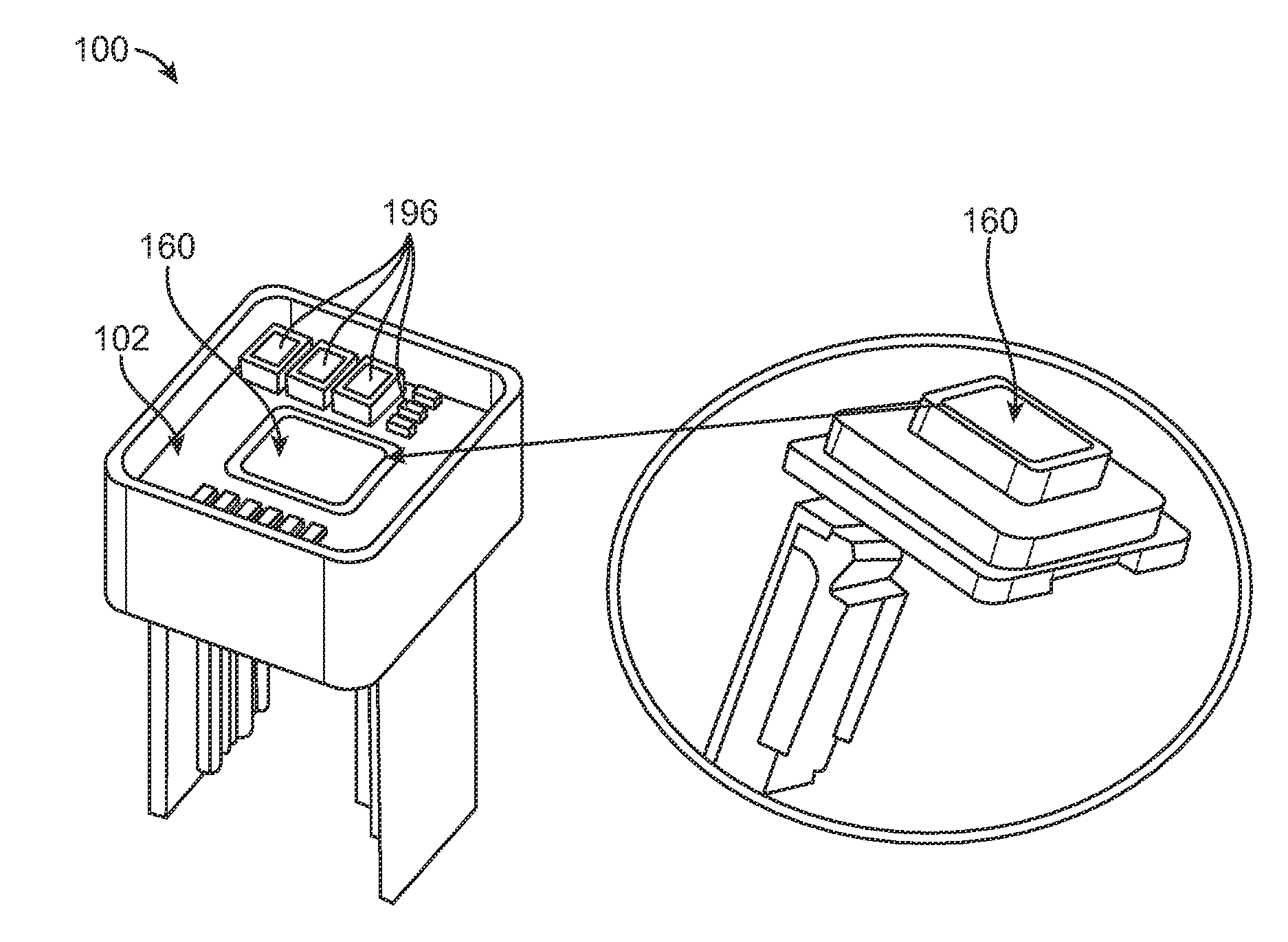
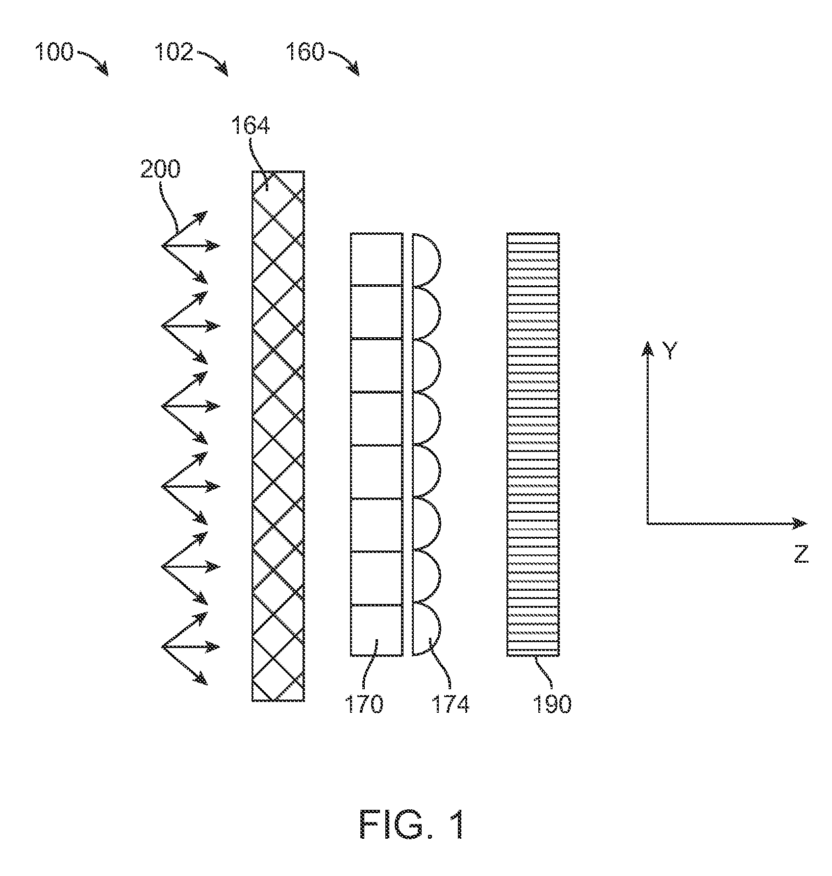
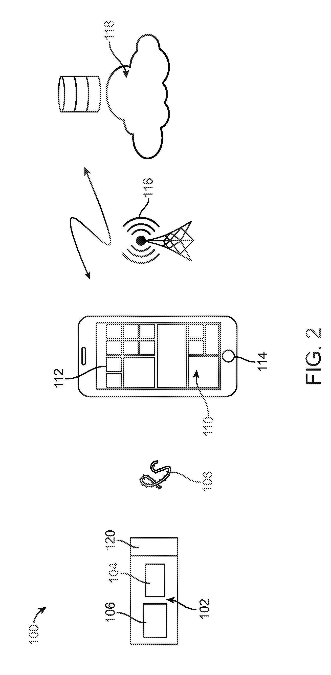
[0009]Embodiments of the present disclosure provide an improved spectrometer, such as a low-cost, rugged spectrometer suitable for combination with consumer devices and cloud computing. In many embodiments, the spectrometer comprises a plurality of isolated optical channels comprising a plurality of isolated optical paths. The isolated optical paths have the advantage of decreasing cross-talk among the optical paths and allowing the spectrometer to have a decreased length with increased resolution. In many embodiments, the isolated optical paths comprise isolated parallel optical paths that allow the length of the device to be decreased substantially. In many embodiments, each isolated optical path extends from a filter of a filter array, through a lens of a lens array, through a channel of a support array, to a region of a sensor array. Each region of the sensor array comprises a plurality of sensor elements in which a location of the sensor element corresponds to the wavelength of light received based on an angle of light received at the location, the focal length of the lens and the central wavelength of the filter. In many embodiments, a diffuser is located along the optical path prior to the filter array in order to provide at least constant angular distribution of light energy among the filters of the array. In many embodiments, a second diffuser is located along the optical path between the diffuser and the filter at a sufficient distance from the diffuser in order to receive a substantially uniform distribution of light energy across the second diffuser in order to further homogenize the light and provide a constant angular distribution of the light energy transmitted to the filter array.
[0010]In many embodiments, the spectrometer system provides a substantially straight optical axis and a short light path. The straight optical axis and short light path enable production of spectrometers that are small enough and economical enough to fit in devices such as cellular phones, and yet have sufficient sensitivity and resolution (e.g. <10 nm) to obtain useful spectra of complex mixtures.
[0061]The filters in the filter matrix can be arranged in a specific order to minimize cross talk on the detector of light emerging from different filters.
[0067]In many embodiments of the matrix, the overlap can allow stitching of spectra generated by two different filters.
Problems solved by technology
However these instruments have typically been too large and too costly for the consumer market.
Also, the cost of prior spectrometers can be greater than would be ideal.
The prior spectrometers can be somewhat bulky, difficult to transport and the optics can require more alignment than would be ideal in at least some instances.
The prior spectrometers having decreased size and optical path length can have less than ideal resolution, sensitivity and less accuracy than would be ideal.
Method used
Image
Click on the blue label to locate the original text in one second.
Reading with bidirectional positioning of images and text.
Examples
Embodiment Construction
[0093]In the following description, various aspects of the invention will be described. For the purposes of explanation, specific details are set forth in order to provide a thorough understanding of the invention. It will be apparent to one skilled in the art that there are other embodiments of the invention that differ in details without affecting the essential nature thereof. Therefore the invention is not limited by that which is illustrated in the figure and described in the specification, but only as indicated in the accompanying claims, with the proper scope determined only by the broadest interpretation of said claims.
[0094]A better understanding of the features and advantages of the present disclosure will be obtained by reference to the following detailed description that sets forth illustrative embodiments, in which the principles of embodiments of the present disclosure are utilized, and the accompanying drawings.
[0095]The embodiments disclosed herein can be combined in ...
PUM
Abstract
A spectrometer comprises a plurality of isolated optical channels comprising a plurality of isolated optical paths. The isolated optical paths decrease cross-talk among the optical paths and allow the spectrometer to have a decreased length with increased resolution. In many embodiments, the isolated optical paths comprise isolated parallel optical paths that allow the length of the device to be decreased substantially. In many embodiments, each isolated optical path extends from a filter of a filter array, through a lens of a lens array, through a channel of a support array, to a region of a sensor array. Each region of the sensor array comprises a plurality of sensor elements in which a location of the sensor element corresponds to the wavelength of light received based on an angle of light received at the location, the focal length of the lens and the central wavelength of the filter.
Description
CROSS-REFERENCE[0001]The present application is a continuation of U.S. patent application Ser. No. ______, filed on May 1, 2015, entitled “Spectrometry System with Decreased Light Path” (attorney docket no. 45151-702.831), which is a national stage entry of PCT Application PCT / IL2014 / 050688, filed on Jul. 30, 2014, entitled “Spectrometry System and Method, Spectroscopic Devices and Systems” (attorney docket no. 45151-702.601), which claims priority to U.S. Provisional Application Ser. No. 61 / 861,893, filed on Aug. 2, 2013, entitled “Spectrometer System” (attorney docket no. 45151-702.101), U.S. Provisional Application Ser. No. 61 / 923,422, filed on Jan. 3, 2014, entitled “Spectroscopic Devices and Systems” (attorney docket no. 45151-702.102), and U.S. Provisional Application Ser. No. 61 / 985,447 filed on Apr. 28, 2014, entitled “Spectroscopic Devices and Systems” (attorney docket no. 45151-702.103), each of which is incorporated herein by reference in its entirety.INCORPORATION BY REF...
Claims
Application Information
Patent Timeline
Application Date:The date an application was filed.
Publication Date:The date a patent or application was officially published.
First Publication Date:The earliest publication date of a patent with the same application number.
Issue Date:Publication date of the patent grant document.
PCT Entry Date:The Entry date of PCT National Phase.
Estimated Expiry Date:The statutory expiry date of a patent right according to the Patent Law, and it is the longest term of protection that the patent right can achieve without the termination of the patent right due to other reasons(Term extension factor has been taken into account ).
Invalid Date:Actual expiry date is based on effective date or publication date of legal transaction data of invalid patent.
Patent Type & Authority Applications(United States)