Cable assembly having improved configuration for suppressing cross-talk

a cross-talk suppression and cable technology, applied in the field of cable assemblies, can solve the problems that therebetween may have negative effects on the electrical properties of the signal transmitting line, and achieve the effect of improving the structure and reducing the cross-talk

Inactive Publication Date: 2010-02-02
HON HAI PRECISION IND CO LTD
View PDF7 Cites 113 Cited by
  • Summary
  • Abstract
  • Description
  • Claims
  • Application Information

AI Technical Summary

Benefits of technology

[0005]Accordingly, an object of the present invention is to provide a cable assembly having an improved structure that can reduce cross-talk around a mating interface thereof.

Problems solved by technology

However, when signals are transmitted via the pair of stacked PCBs, cross-talk phenomena therebetween may have negative effect on electrical property of a signal transmitting line.

Method used


Image

  • Cable assembly having improved configuration for suppressing cross-talk
  • Cable assembly having improved configuration for suppressing cross-talk
  • Cable assembly having improved configuration for suppressing cross-talk

Examples


Embodiment Construction

[0016]Reference will now be made in detail to the preferred embodiment of the present invention.

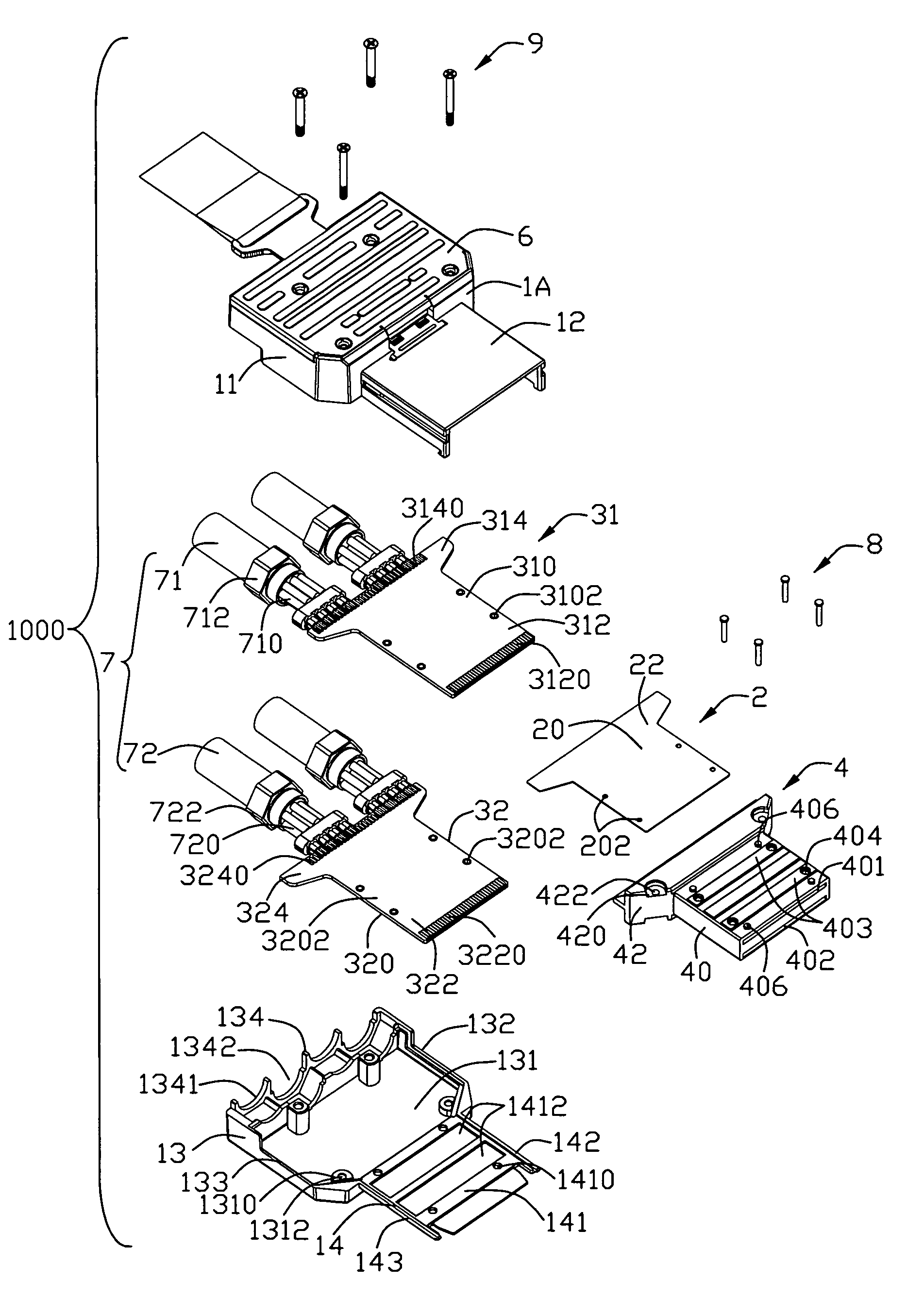
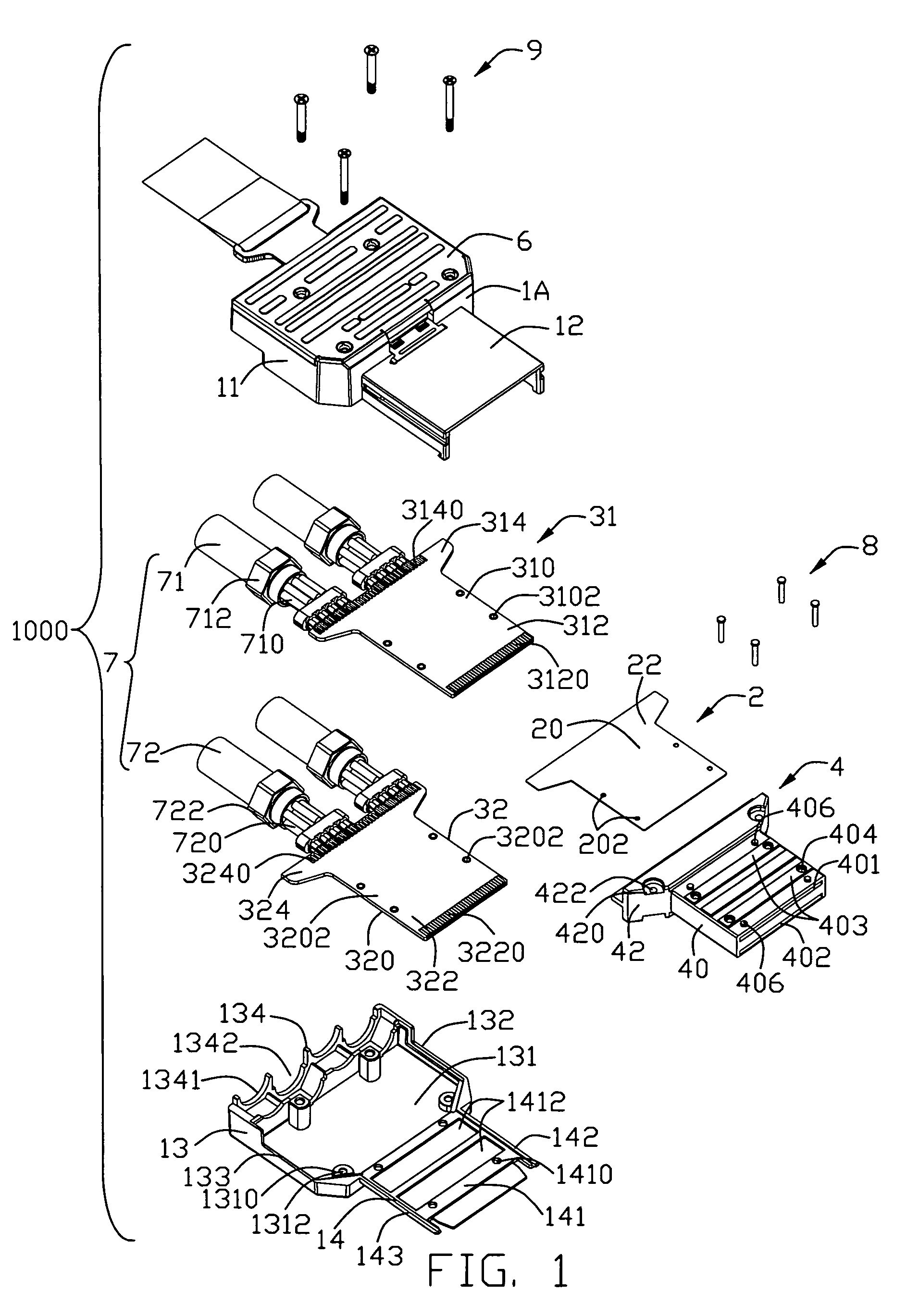
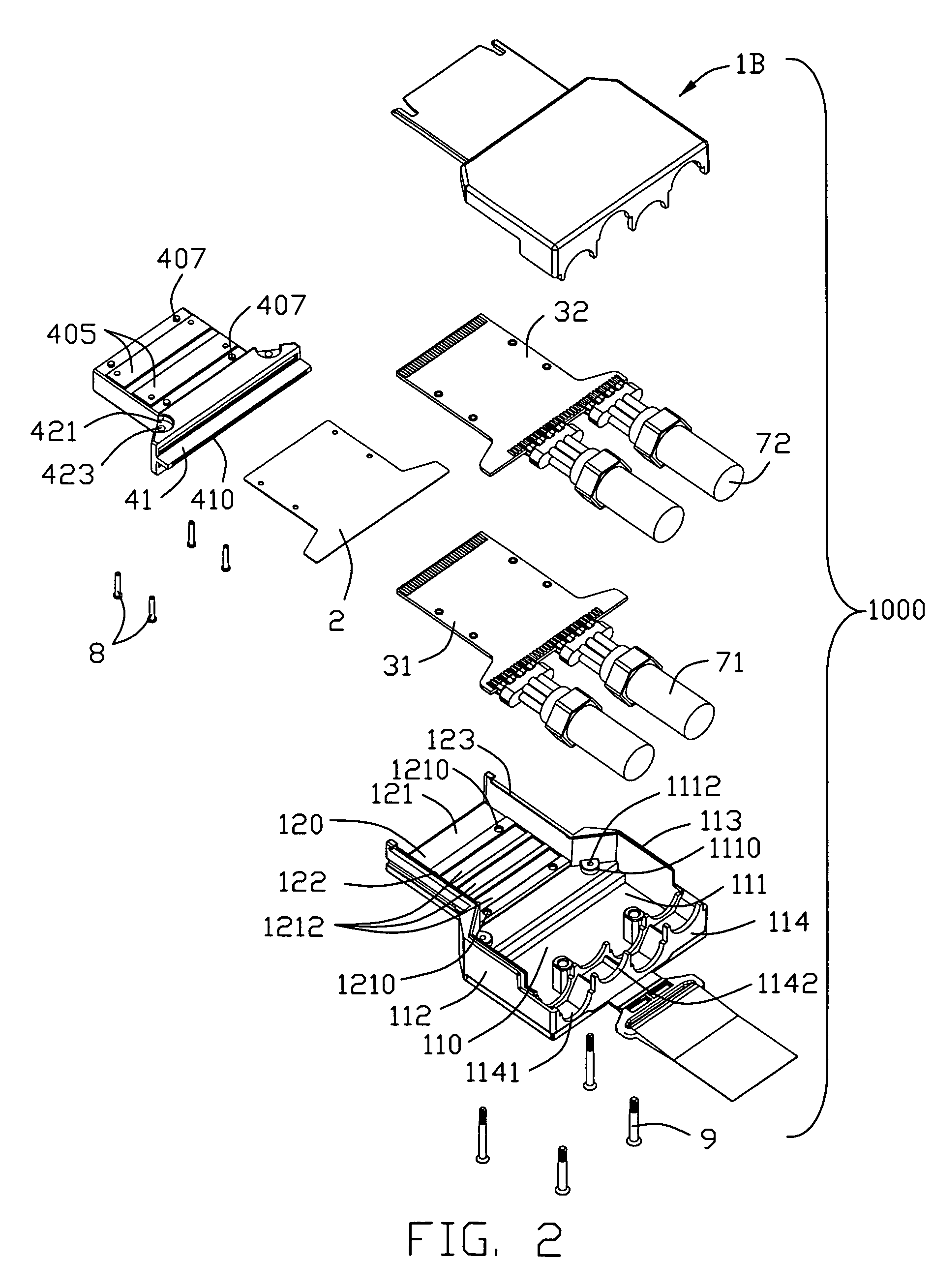
[0017]Referring to FIGS. 1-3 and in conjunction with FIGS. 4-9, a cable assembly 1000 in accordance with the present invention comprises a housing 1, a metallic plate 2, a pair of printed circuit boards (PCBs) 31, 32, a spacer 4, a latch mechanism 5, a cap member 6 and four cables 7.

[0018]The housing 1 having a first shield part 1A and a second shield part 1B together enclosing a receiving space 10 therein. Both the first shield part 1A and the second shield part 1B are made of metallic material and formed by die-cast process.

[0019]The first shield part 1A comprises an expanded first base portion 11 and a relative slim first mating portion 12 extending forwardly from a front edge of the first base portion 11. The first base portion 11 has a top wall 111, a pair of side walls 112, 113 and a rear wall 114 together forming a hollow portion 110. Four cavities 1141, 1142 are defined in a rear ...


PUM


Abstract

A cable assembly (1000) includes a housing (1) has a receiving space (10), said receiving space including a hollow portion and a mating port located in front of the hollow portion; a spacer (4) located in the receiving space; a first and second printed circuit boards (31, 32) partially enclosed within the spacer and arranged apart from one another, both the first and second printed circuit boards having mating interfaces extending into the mating port and mounting portions disposed in the hollow portion; a metallic plate (2) assembled to the spacer and disposed between the pair of first and second printed circuit boards; a plurality of cables (7) coupled to the mounting portions of the pair of first and second printed circuit boards, respectively.

Description

FIELD OF THE INVENTION[0001]The present invention generally relates to a cable assembly, and more particularly to a cable assembly having an improved structure for suppressing cross-talk to acquire better signal transmission property.DESCRIPTION OF PRIOR ART[0002]PCI Express, officially abbreviated as PCI-E or PCIe, is a computer expansion card interface format introduced by Intel in 2004. It was designed to replace the general-purpose PCI expansion bus, the high-end PCI-X bus and the AGP graphics card interface. Unlike previous PC expansion interfaces, rather than being merely a bus, it is configured around point-to-point full duplex serial links called lanes. In PCIe 1.1 (the most common version as of 2007) each lane carries 250 MB / s in each direction.[0003]PCI Express External Cabling which extends the PCI Express interconnects architecture “outside the box.” Cables using the PCIe technology will be used for external applications, as well as applications internal to an enclosure ...

Claims


Application Information

Patent Timeline
Patent Type & Authority Patents(United States)
IPC IPC(8): H01R12/00
CPCH01R12/62H01R13/514H01R13/6658H01R13/6471H01R13/6595Y10S439/941H01R13/6593
Inventor WU, JERRY
Owner HON HAI PRECISION IND CO LTD
Why Eureka
Try Eureka