Printed circuit board and method of reducing crosstalk in a printed circuit board

a printed circuit board and crosstalk technology, applied in the field of printed circuit boards, can solve the problems of unsatisfactory crosstalk between signals, increased crosstalk problem, and barrier to effective error-free communication, so as to reduce crosstalk, reduce crosstalk, and reduce crosstalk.

Active Publication Date: 2007-07-03
XILINX INC
View PDF4 Cites 114 Cited by
  • Summary
  • Abstract
  • Description
  • Claims
  • Application Information

AI Technical Summary

Benefits of technology

[0008]The embodiments of the present invention relate to an improved printed circuit board having additional rows of ground vias to reduce crosstalk in the board. A printed circuit board according to one embodiment of the present invention comprises a first row of vias and a second row of vias, each having a plurality of signal vias. The circuit board also comprises a plurality of rows of vias being coupled to a ground plane between the first and second rows of signal vias. According to one embodiment, the plurality of rows of vias being coupled to a ground plane comprise rows of vias having different sizes. Some of the vias are designed to receive a component, while others are generally smaller and designed to provide a return current path for the signal vias.
[0009]A method of reducing crosstalk in a printed circuit board is also described. The method generally comprises steps of providing a plurality of rows of signal vias coupling predetermined leads of a plurality of components to signal vias; coupling ground leads of the plurality of components to a plurality of rows of ground vias; and providing a return path for signals on the signal vias by way of rows of ground vias adjacent to the rows of signal vias. A method for forming a printed circuit board designed to reduce crosstalk is also disclosed.

Problems solved by technology

A problem that results from this arrangement is that the electric and magnetic fields of signals traversing through the connector interact with one another, causing an undesirable crosstalk between the signals.
As data rates continue to increase, the problem of crosstalk will also increase.
At such high frequencies, crosstalk of signals becomes a barrier to effective error free communication.

Method used


Image

  • Printed circuit board and method of reducing crosstalk in a printed circuit board
  • Printed circuit board and method of reducing crosstalk in a printed circuit board
  • Printed circuit board and method of reducing crosstalk in a printed circuit board

Examples


Embodiment Construction

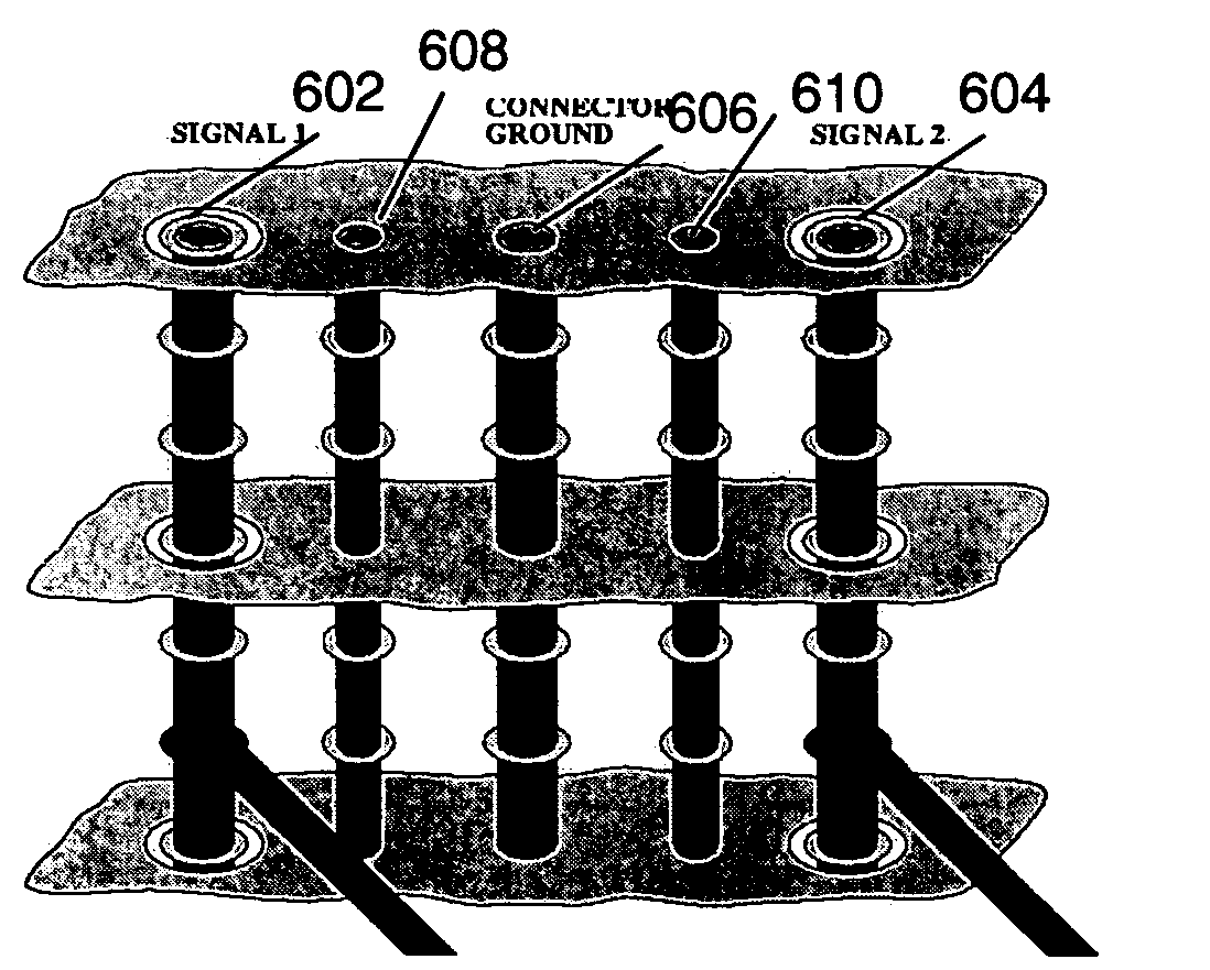
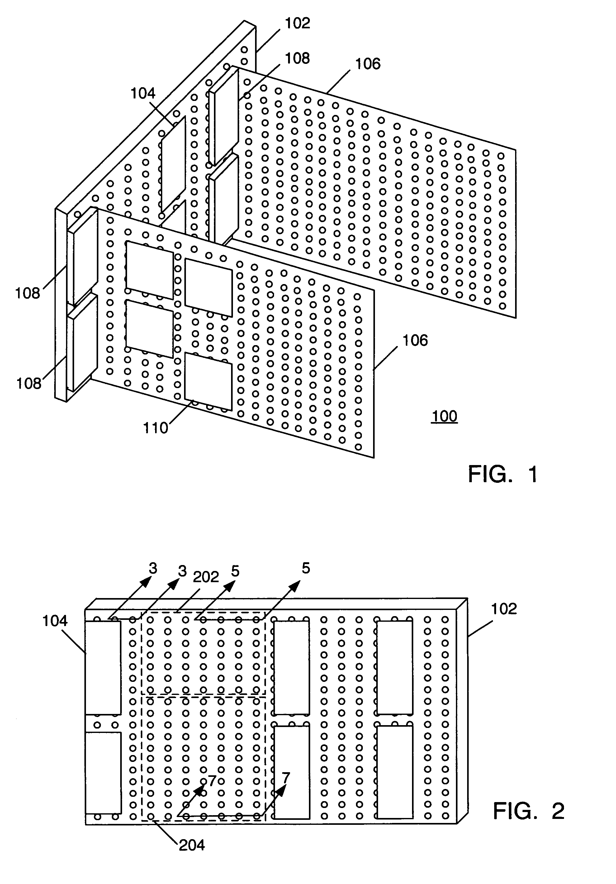
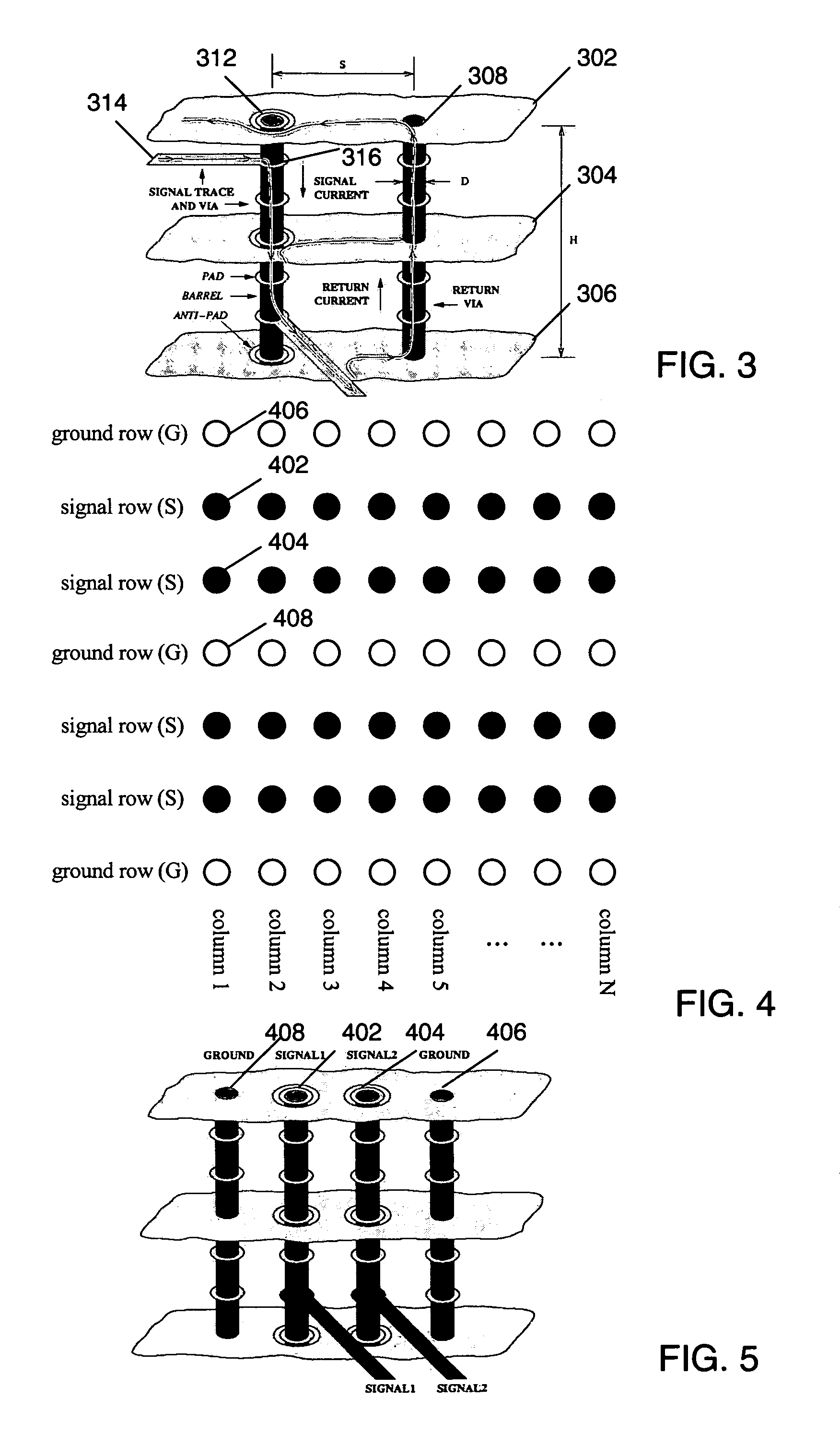
[0020]Turning now to FIG. 1, a perspective view of a printed circuit board assembly according to an embodiment of, the present invention is shown. In particular, a printed circuit board 102 comprising a backplane has a plurality of connectors 104. The plurality of connectors are adapted to receive other printed circuit boards 106, such as by way of corresponding connectors 108 on the printed circuit boards 106. As will be described more detail reference to later figures, the embodiments of the present invention enable reduced crosstalk in the printed circuit board by providing additional ground vias which provide additional return paths for signals. As shown in FIG. 2, the top plan view shows printed circuit board 102 of FIG. 1 having a number of vias arranged on the printed circuit board. The printed circuit board could be any type of multi-layer printed circuit board having vias, and finds particular application in a backplane of a circuit board assembly for enabling the transmiss...


PUM


Abstract

The embodiments of the present invention relate to an improved printed circuit board having additional rows of ground vias to reduce crosstalk in the board. A printed circuit board according to one embodiment of the present invention comprises a first row of vias and a second row of vias, each having a plurality of signal vias. The circuit board also comprises a plurality of rows of vias being coupled to a ground plane between the first row of signal vias and the second row of signal vias. According to one embodiment, the plurality of rows of vias being coupled to a ground plane comprise rows of vias having different sizes. Some of the vias are designed to receive a component, while others are generally smaller and designed to provide a return current path for the signal vias.

Description

FIELD OF THE INVENTION[0001]The present invention relates generally to printed circuit boards, and in particular, to a method of reducing crosstalk in a printed circuit board.BACKGROUND OF THE INVENTION[0002]Current and future telecommunication switches make extensive use of backplane connectors. These connectors are used to join various system components of a communication switch together. Due to the strong desire on the part of the marketplace for high pin density, these connectors are frequently constructed such that signal pairs are placed in close proximity to one another. A problem that results from this arrangement is that the electric and magnetic fields of signals traversing through the connector interact with one another, causing an undesirable crosstalk between the signals. As data rates continue to increase, the problem of crosstalk will also increase.[0003]High speed serial backplanes are a common media used in the creation of network switches. The backplane is a very t...

Claims


Application Information

Patent Timeline
Patent Type & Authority Patents(United States)
IPC IPC(8): H01R12/16
CPCH05K1/0219H01R12/523H01R13/6471H05K3/429H05K2201/044H05K2201/09236H05K2201/09609H05K2201/09618H05K2201/10189
Inventor BIBEE, MATTHEW L.
Owner XILINX INC
Why Eureka
Try Eureka