High speed, high density electrical connector

a high-speed, electrical connector technology, applied in the direction of coupling contact members, coupling device connections, coupling protective earth/shielding arrangements, etc., can solve the problems of increasing the possibility of electrical noise being generated in the connector, reducing the normal mating force of the connector, and reducing the insertion force. , the effect of improving the connection

Active Publication Date: 2012-08-23
AMPHENOL CORP
View PDF7 Cites 98 Cited by
  • Summary
  • Abstract
  • Description
  • Claims
  • Application Information

AI Technical Summary

Benefits of technology

[0010]Accordingly, it is an object of the invention to provide a broadside coupled connector assembly having two sets of conductors, each in a separate plane. It is a further object of the invention to provide a connector assembly having an improved connection at the mating interface between a daughter card connector and a backplane connector, with reduced insertion force and controlled higher normal mating force. It is a further object of the invention to provide a connector assembly having improved coupling at the mating interface to provide impedance matching and avoid undesirable electrical characteristics. It is a further object of the invention to provide a connector assembly which provides desirable electrical characteristics such as those achieved by a twinaxial cable. These characteristics include good impedance control, balance of each differential pair including low in-pair skew and a high level of isolation between different pairs, while being suitable for large volume production such as by stamping and molding operations.

Problems solved by technology

Electronic systems have generally become smaller, faster and functionally more complex.
As signal frequencies increase, there is a greater possibility of electrical noise being generated in the connector, such as reflections, crosstalk and electromagnetic radiation.

Method used


Image

  • High speed, high density electrical connector
  • High speed, high density electrical connector
  • High speed, high density electrical connector

Examples


Embodiment Construction

[0046]In describing a preferred embodiment of the invention illustrated in the drawings, specific terminology will be resorted to for the sake of clarity. However, the invention is not intended to be limited to the specific terms so selected, and it is to be understood that each specific term includes all technical equivalents that operate in similar manner to accomplish a similar purpose.

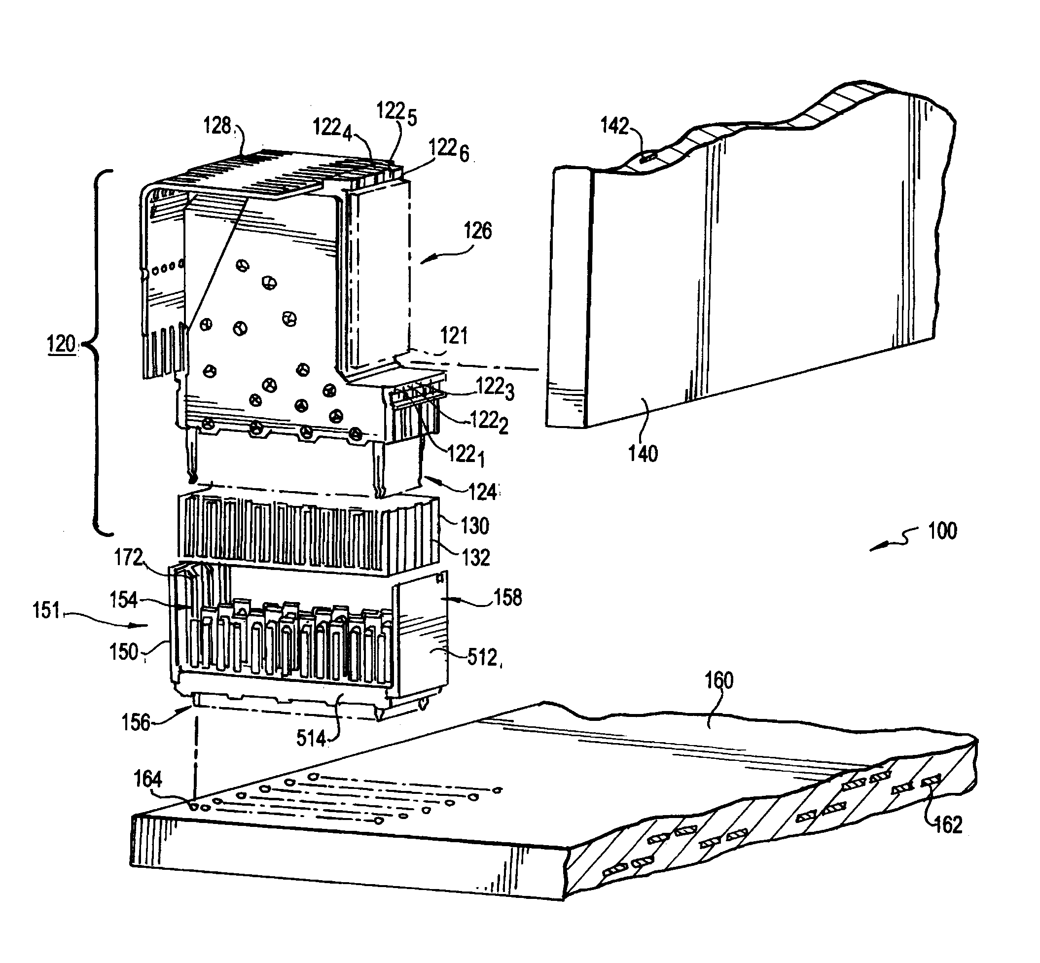
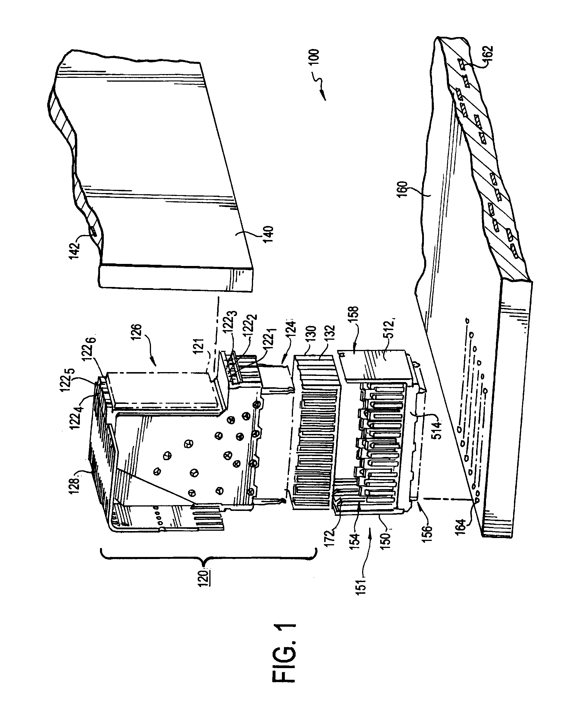
[0047]Turning to the drawings, FIG. 1 shows an electrical interconnection system 100 with two connectors, namely a daughter card connector 120 and a backplane connector 150. The daughter card connector 120 is designed to mate with the backplane connector 150, creating electronically conducting paths between the backplane 160 and the daughter card 140. Though not expressly shown, the interconnection system 100 may interconnect multiple daughter cards having similar daughter card connectors that mate to similar backplane connections on the backplane 160. Accordingly, the number and type of subassembl...


PUM


Abstract

A broadside coupled connector assembly has two sets of conductors, each separate planes. By providing the same path lengths, there is no skew between the conductors of the differential pair and the impedance of those conductors is identical. The conductor sets are formed by embedding the first set of conductors in an insulated housing having a top surface with channels. The second set of conductors is placed within the channels so that no air gaps form between the two sets of conductors. A second insulated housing is filled over the second set of conductors and into the channels to form a completed wafer. The ends of the first and second sets of conductors and the blades are jogged in both an x- and y-coordinate to reduce crosstalk and improve electrical performance.

Description

RELATED APPLICATION[0001]This application claims the benefit of U.S. Prov. App. No. 61 / 444,366, filed Feb. 18, 2011 and U.S. Prov. App. No. 61 / 449,509, filed Mar. 4, 2011, the entire contents of which are incorporated herein by reference.BACKGROUND OF THE INVENTION[0002]1. Field of Invention[0003]This invention relates generally to electrical interconnection systems and more specifically to improved signal integrity in interconnection systems, particularly in high speed electrical connectors.[0004]2. Discussion of Related Art[0005]Electrical connectors are used in many electronic systems. It is generally easier and more cost effective to manufacture a system on several printed circuit boards (“PCBs”) that are connected to one another by electrical connectors than to manufacture a system as a single assembly. A traditional arrangement for interconnecting several PCBs is to have one PCB serve as a backplane. Other PCBs, which are called daughter boards or daughter cards, are then conn...

Claims


Application Information

Patent Timeline
Patent Type & Authority Applications(United States)
IPC IPC(8): H01R13/648H01R24/00
CPCH01R13/6461H01R13/04H01R13/6587H01R13/6473H01R13/02
Inventor COHEN, THOMAS S.REN, HUILINCARTIER, JR., MARC B.DO, TRENT K.GAILUS, MARK W.
Owner AMPHENOL CORP
Why Eureka
Try Eureka