Track for metal stud walls

a technology of metal stud walls and tracks, applied in the field of tracks, can solve the problems of increasing the cost of manufacturing tracks and no support structure provided

Active Publication Date: 2007-08-23
BAILEY METAL PROD
View PDF26 Cites 80 Cited by
  • Summary
  • Abstract
  • Description
  • Claims
  • Application Information

AI Technical Summary

Problems solved by technology

Such designs of tracks do suffer drawbacks in that the additional structure increases the costs of manufacturing the track.
In addition, should the stud have to be installed in a position other than the regular spacing, there is no support structure provided and the installer has to once again measure for the placement of the stud.

Method used


Image

  • Track for metal stud walls
  • Track for metal stud walls
  • Track for metal stud walls

Examples


Embodiment Construction

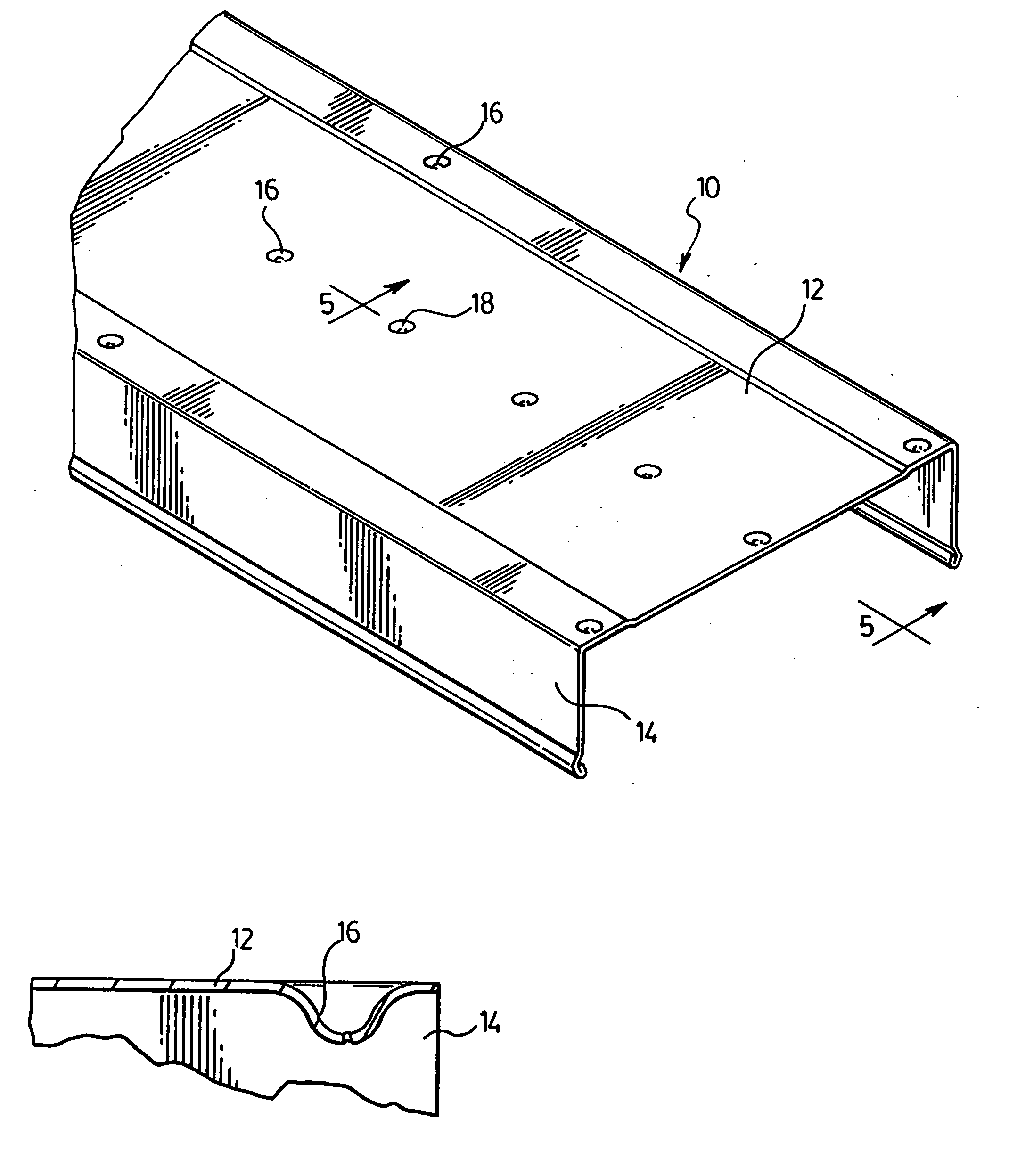
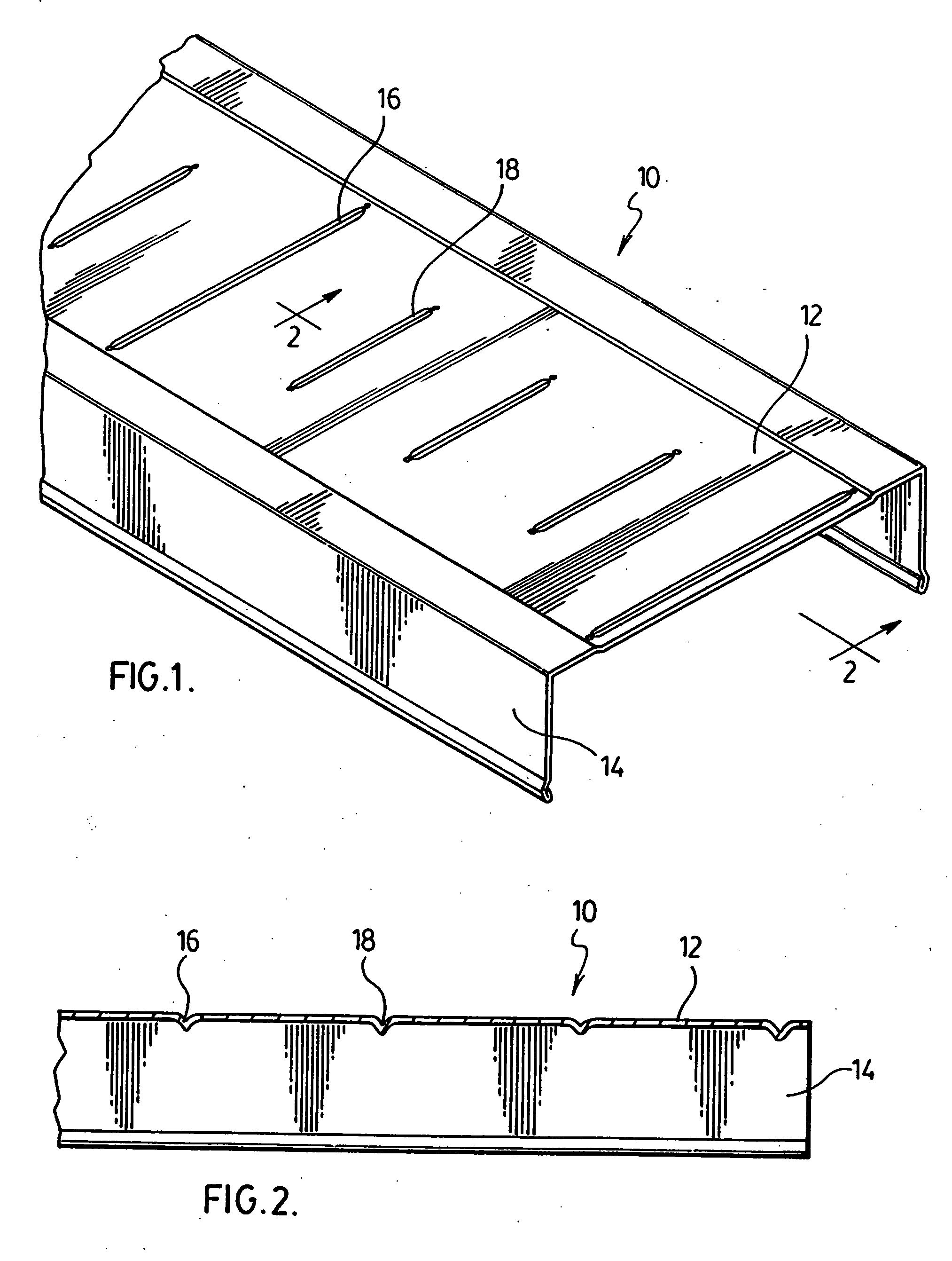
[0013] A first preferred embodiment of a track for use in metal stud walls is illustrated in FIGS. 1 and 2, generally indicated by the numeral 10. Track 10 has a base 12 and two upstanding side walls 14 extending along either side of the base 10. Base 12 is provided with a plurality of embossed indicator means 16 and 18 evenly placed along the length of the base 12. The spacing of the indicator means 16 and 18 provides a guide for the proper spacing of studs 20 placed in the track 10 as described below.

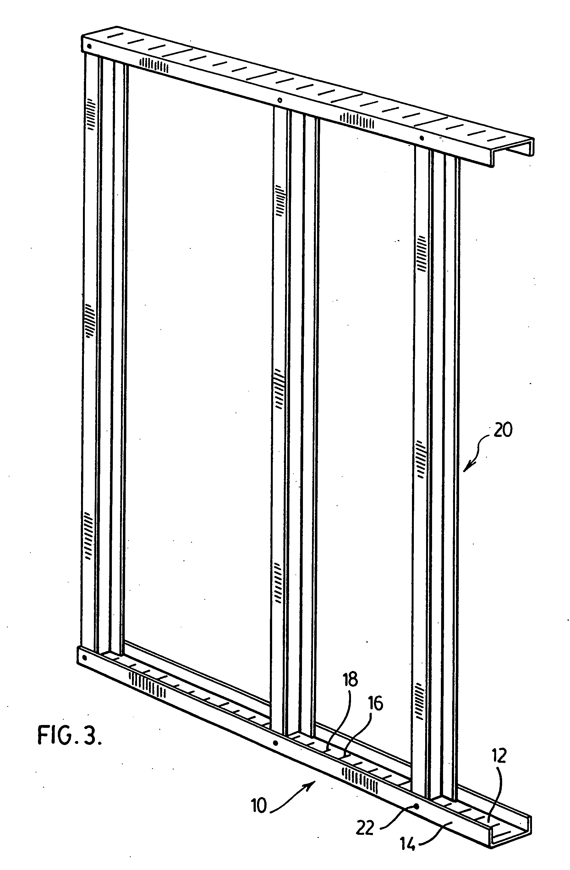
[0014] The use of the track 10 of the present invention for construction of a metal stud wall is illustrated in FIG. 3. In a typical construction of a metal stud wall, the bottom and top tracks 10 are generally fastened to the floor and ceiling respectively and the vertical studs 20 bridging the two tracks 10 are placed in the channels of the tracks 10 and fastened to the tracks 10. In order to fasten the tracks 10 to the floor and ceiling respectively, the track 10 is positioned in ...


PUM


Abstract

The present invention provides for track for use in constructing metal stud walls. The track is a generally U-shaped channel having a base and upstanding side walls extending along either side of the base. The base is provided with a plurality of embossed indicator means evenly spaced along the length of the base. The spacing of the embossed indicator means provides a guide for the proper spacing of the studs placed in the base.

Description

FIELD OF THE INVENTION [0001] The present invention is directed to track for use in metal stud walls and particularly to a track which increases the ease of installation of metal stud walls. BACKGROUND OF THE INVENTION [0002] Metal stud walls are commonly used, especially in commercial, institutional and industrial construction, because of their fire resistance and non-warping characteristics. Such stud walls generally have a bottom and top track attached to the floor and ceiling respectively and a plurality of spaced apart studs extending vertically between the tracks. In a typical installation, the studs are spaced 16 or 24 inches apart to accommodate the 4 foot widths of wall covering material such as drywall or other sheets. In order to make the installation of the studs easier, a number of tracks have been developed with one or more structures on the upstanding walls of the track that hold the studs in the track at the proper spacing. Examples of such structures are shown in U....

Claims


Application Information

Patent Timeline
Patent Type & Authority Applications(United States)
IPC IPC(8): E04H3/00
CPCE04B2/7457E04B2/767E04B2/789E04C2003/0473E04C2003/0421E04C2003/0434E04C3/07
Inventor RICE, JOHN
Owner BAILEY METAL PROD
Why Eureka
Try Eureka