Accelerator pedal for a vehicle

a technology of accelerator pedals and vehicles, applied in the direction of mechanical control devices, process and machine control, instruments, etc., can solve the problems of insufficiently emulating the tactile response of conventional accelerator pedals or too expensive prior art systems

Inactive Publication Date: 2007-08-23
CTS CORP ELKHART
View PDF4 Cites 62 Cited by
  • Summary
  • Abstract
  • Description
  • Claims
  • Application Information

AI Technical Summary

Benefits of technology

[0009]These and other objects, features and advantages will b

Problems solved by technology

In this regard, prior art systems are either too costly or inadequat

Method used


Image

  • Accelerator pedal for a vehicle
  • Accelerator pedal for a vehicle
  • Accelerator pedal for a vehicle

Examples


Embodiment Construction

[0022]While this invention is susceptible to embodiment in many different forms, this specification and the accompanying drawings disclose several forms as examples of the invention. The invention is not intended to be limited to the embodiments so described, however. The scope of the invention is identified in the appended claims.

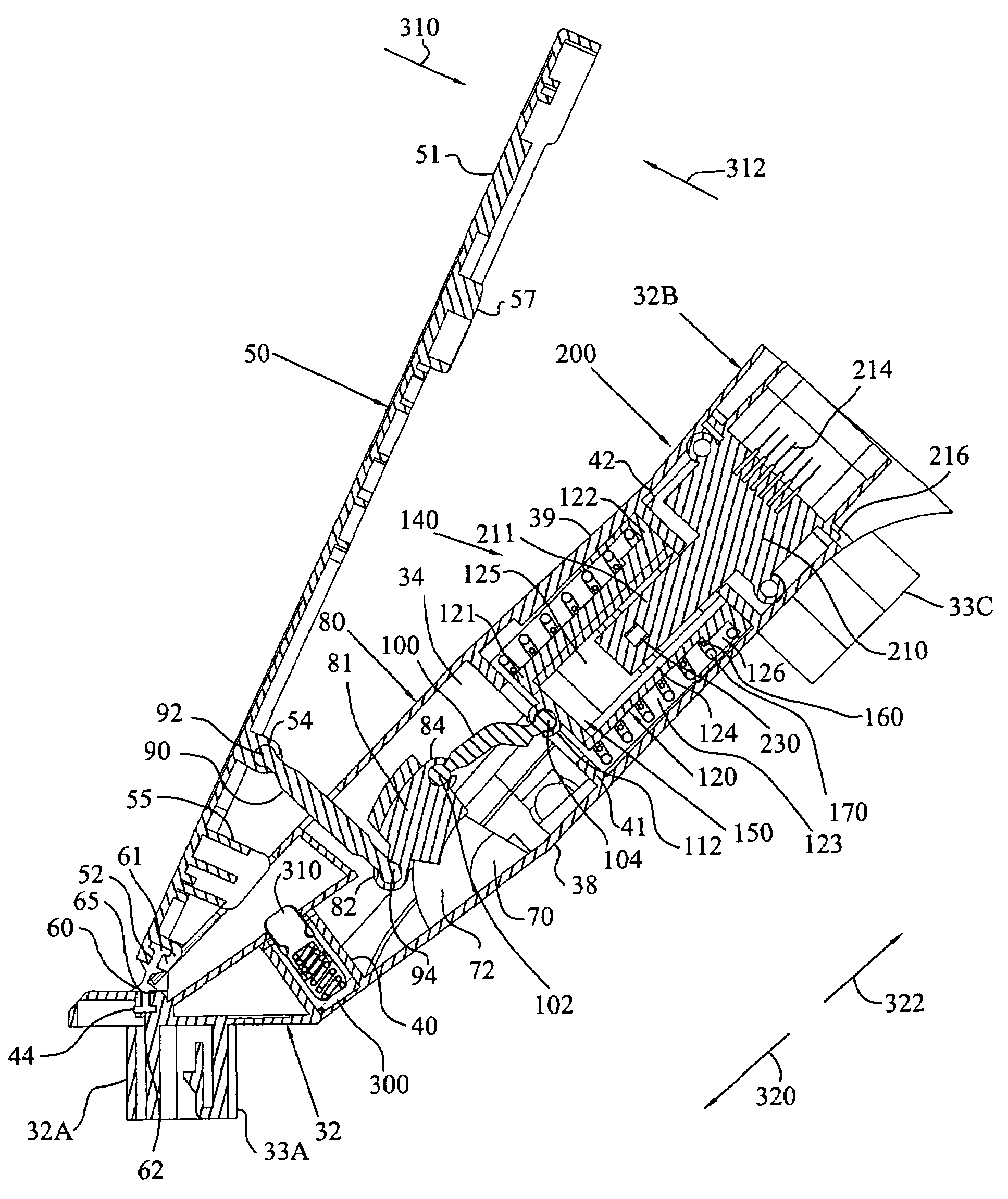
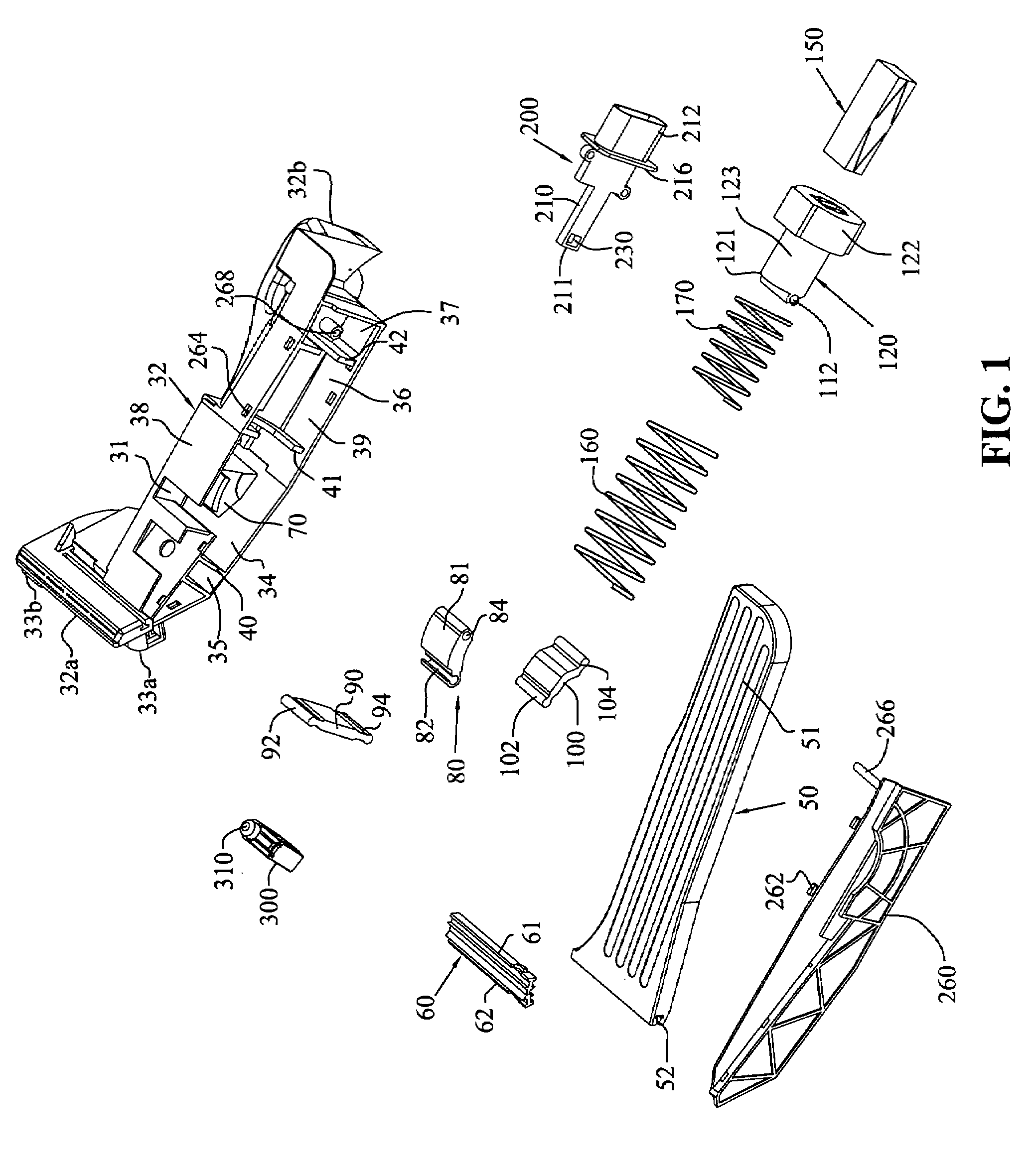
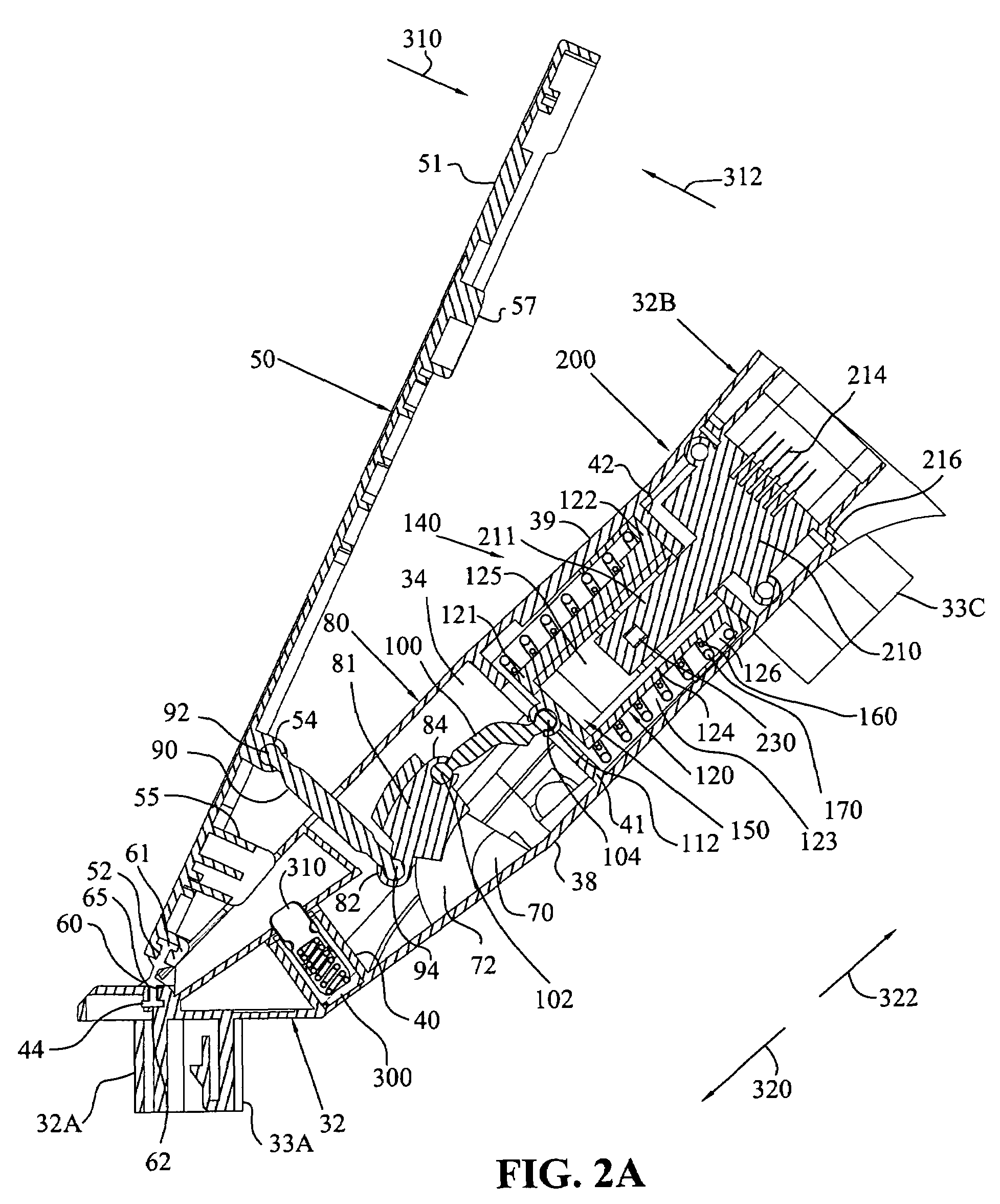
[0023]Referring to FIGS. 1-6, a non-contacting accelerator pedal assembly 20 according to the present invention includes a housing 32 and a pedal arm 50 that is rotatably mounted to housing 32. Housing 32 can contain the components of the pedal assembly. Housing 32 would typically be mounted to a floor of a vehicle. Housing 32 can be formed from molded plastic. Housing 32 can include mounting points 33A, 33B and 33C.

[0024]Housing 32 can include several cavities. The cavities include brake pad cavity 34, a kickdown cavity 35, a magnet cavity 36 and a connector cavity 37. Housing 32 has ends, 32A, 32B, an upper wall 38, lower wall 39 and slot 33. A wall 40 s...


PUM


Abstract

A pedal assembly for mounting to the floor of a vehicle. The pedal assembly includes a housing and a pedal arm that is coupled to the housing. A friction generating assembly is coupled with the pedal arm. A sensor is coupled to the friction generating assembly. The sensor is responsive to the movement of the pedal arm to provide an electrical signal that is representative of pedal arm displacement.

Description

CROSS-REFERENCE TO RELATED AND CO-PENDING APPLICATIONS[0001]This application claims priority to the filing date of U.S. Provisional Patent Application Ser. No. 60 / 764,693, filed on Feb. 2, 2006, entitled, “Floor Mounted Pedal and Sensor Assembly”, the contents of which are explicitly incorporated by reference in entirety.FIELD OF THE INVENTION[0002]This invention relates to a pedal mechanism. In particular, the pedal may be an accelerator pedal in a vehicle.BACKGROUND OF THE INVENTION[0003]Automobile accelerator pedals have conventionally been linked to engine fuel subsystems by a cable, generally referred to as a Bowden cable. While accelerator pedal designs vary, the typical return spring and cable friction together create a common and accepted tactile response for automobile drivers. For example, friction between the Bowden cable and its protective sheath otherwise reduce the foot pressure required from the driver to hold a given throttle position. Likewise, friction prevents roa...

Claims


Application Information

Patent Timeline
IPC IPC(8): G05G1/14G05G1/38
CPCB60K26/02Y10T74/20888G05G5/03G05G1/38
Inventor CAMPBELL, ANDREW
Owner CTS CORP ELKHART
Why Eureka
Try Eureka