Eureka AIR delivers breakthrough ideas for toughest innovation challenges, trusted by R&D personnel around the world.

Method for setting initial compensation value in sensor complex module

Inactive Publication Date: 2007-08-23
SAMSUNG ELECTRO MECHANICS CO LTD
View PDF3 Cites 4 Cited by
  • Summary
  • Abstract
  • Description
  • Claims
  • Application Information

AI Technical Summary

Benefits of technology

[0017]An object of the present invention is to provide a method for setting an initial compensation value of a sensor complex module, which can perform automatic and quick compensation for a gradient error by allowing the sensor complex module having an acceleration sensor at a main board to automatically and quickly measure the gradient error without using a separate measuring controller, so that productivity and convenience in use can be improved.

Problems solved by technology

At the time of bonding, the bonding height may become uneven between right and left or between front and back because of physical influence.
For this reason, the sensor is randomly inclined, causing an error in an output value.
For example, the output value of the acceleration sensor may increase or decrease in proportion to a gradient, and in such a manner, a terrestrial magnetism sensor also makes an error in an output value.
In the method for setting an initial compensation value of the conventional sensor complex module, an error generated by, for example, defective mounting is measured and compensated through such complicated processes using the maximum-minimum measuring device, which makes the error compensation complicated.
For this reason, the overload of a manufacturing line may occur, and thus productivity may be lowered.

Method used


Image

  • Method for setting initial compensation value in sensor complex module
  • Method for setting initial compensation value in sensor complex module
  • Method for setting initial compensation value in sensor complex module

Examples


Embodiment Construction

[0033]Reference will now be made in detail to the preferred embodiments of the present invention, examples of which are illustrated in the accompanying drawings.

[0034]FIG. 3 is a block diagram of a sensor complex module according to the present invention.

[0035]Referring to FIG. 3, a sensor complex module 100 according to the present invention includes an acceleration sensor 110, a memory 120, and a controller 130.

[0036]The acceleration sensor 110 measures the acceleration of a main board or a product mounted to a mobile terminal such as a cellular phone. Here, since the acceleration is proportional to shakes of the main board, the acceleration sensor 110 can measure shakes or movements of the corresponding mobile terminal. Here, the acceleration sensor 110 may be a two-axial acceleration sensor or a three-axial acceleration sensor.

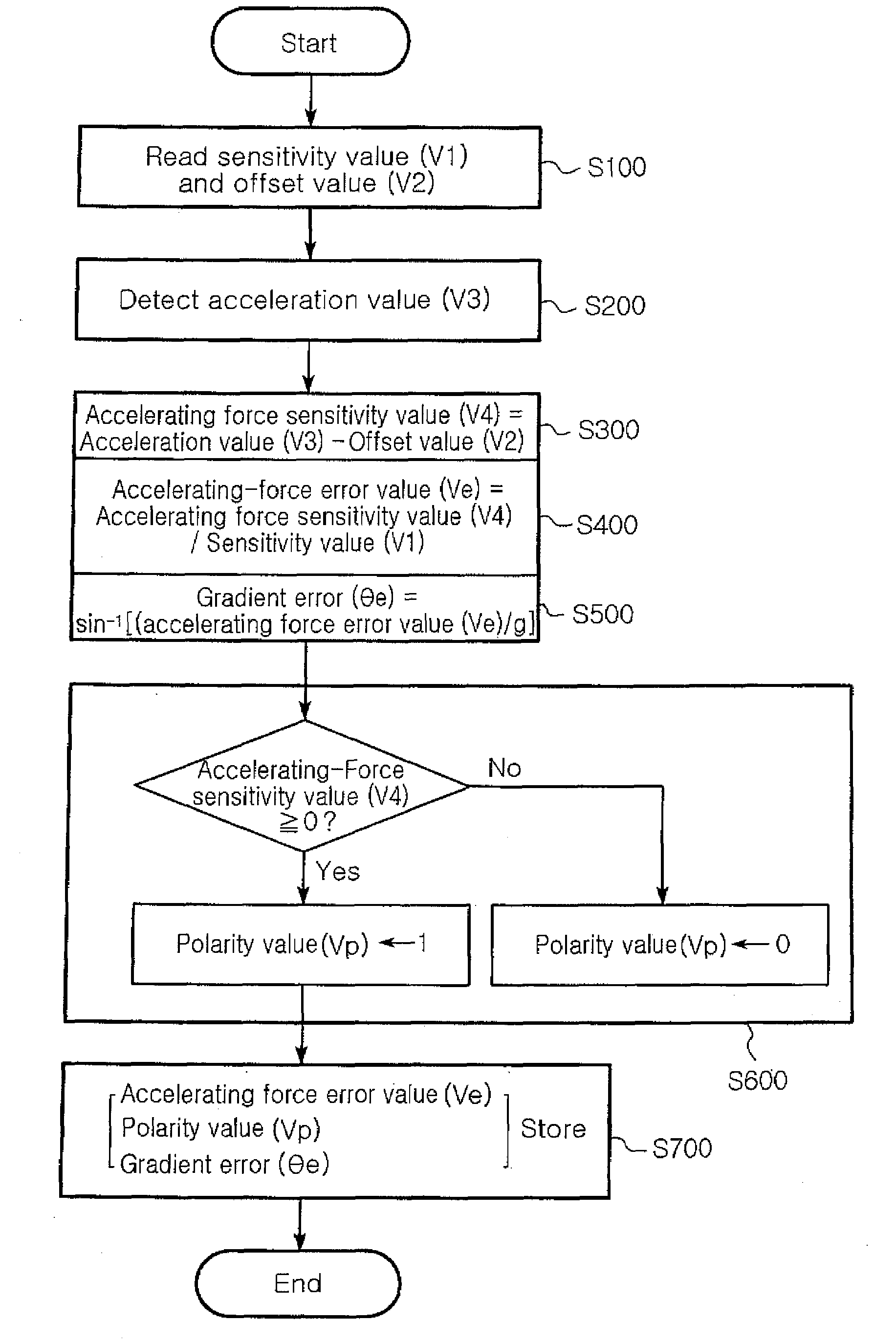
[0037]The memory 120 stores a sensitivity value (V1) and an offset value (V2) preset according to the performance of the acceleration sensor, and stores a...


PUM


Abstract

A method for setting an initial compensation value of a sensor complex module is provided. The method for setting the initial compensation value of the sensor complex module including an acceleration sensor, a memory, and a controller that performs the setting of the initial compensation value, includes the following steps. A preset sensitivity value and an offset value are read from the memory, and an acceleration value is detected using the acceleration sensor. Then, an accelerating-force sensitivity value is calculated using the acceleration value and the offset value, and an accelerating-force error value is calculated using the accelerating-force sensitivity value and the sensitivity value. A gradient error value is calculated using the accelerating-force error value and the acceleration of gravity, and a polarity value is set according to the accelerating-force sensitivity value. The accelerating-force error value, the gradient error value and the polarity value are stored in the memory, and the stored values are set as the initial compensation value.

Description

RELATED APPLICATION[0001]The present application is based on, and claims priority from, Korean Application Number 2006-16850, filed Feb. 21, 2006, the disclosure of which is hereby incorporated by reference herein in its entirety.BACKGROUND OF THE INVENTION[0002]1. Field of the Invention[0003]The present invention relates to a method for setting an initial compensation value of a sensor complex module applied to a mobile terminal such as a cellular phone, and more particularly, to a method for setting an initial compensation value of a sensor complex module, which can perform automatic and quick compensation for a gradient error. In the method, the sensor complex module having an acceleration sensor at a main board automatically and quickly measures the gradient error without using a separate measuring controller, thereby improving productivity and convenience in use.[0004]2. Description of the Related Art[0005]A mobile terminal such as a cellular phone provided with an inertial sen...

Claims


Application Information

Patent Timeline
IPC IPC(8): F02M51/00G06F19/00
CPCG01P21/00G01P15/18B02C18/22B02C18/2216B02C18/24
Inventor CHAE, KYOUNG SOOHAHM, GHUNKIM, HYUN JOONCHO, SUNG WHAN
Owner SAMSUNG ELECTRO MECHANICS CO LTD
Why Eureka
Eureka Blog
Learn More