Air bag door

a technology for air bags and doors, applied in the direction of vehicular safety arrangments, pedestrian/occupant safety arrangements, vehicle components, etc., can solve the problem of requiring large energy to open the door panels, and achieve the effect of adequate breakag

Inactive Publication Date: 2007-08-30
INOAC CORP
View PDF18 Cites 9 Cited by
  • Summary
  • Abstract
  • Description
  • Claims
  • Application Information

AI Technical Summary

Benefits of technology

[0023]Setting the inclination angle of the groove portion within a predetermin

Problems solved by technology

Because of a variation in the break position, the air bag door AD 1 may not

Method used


Image

  • Air bag door
  • Air bag door
  • Air bag door

Examples


embodiment

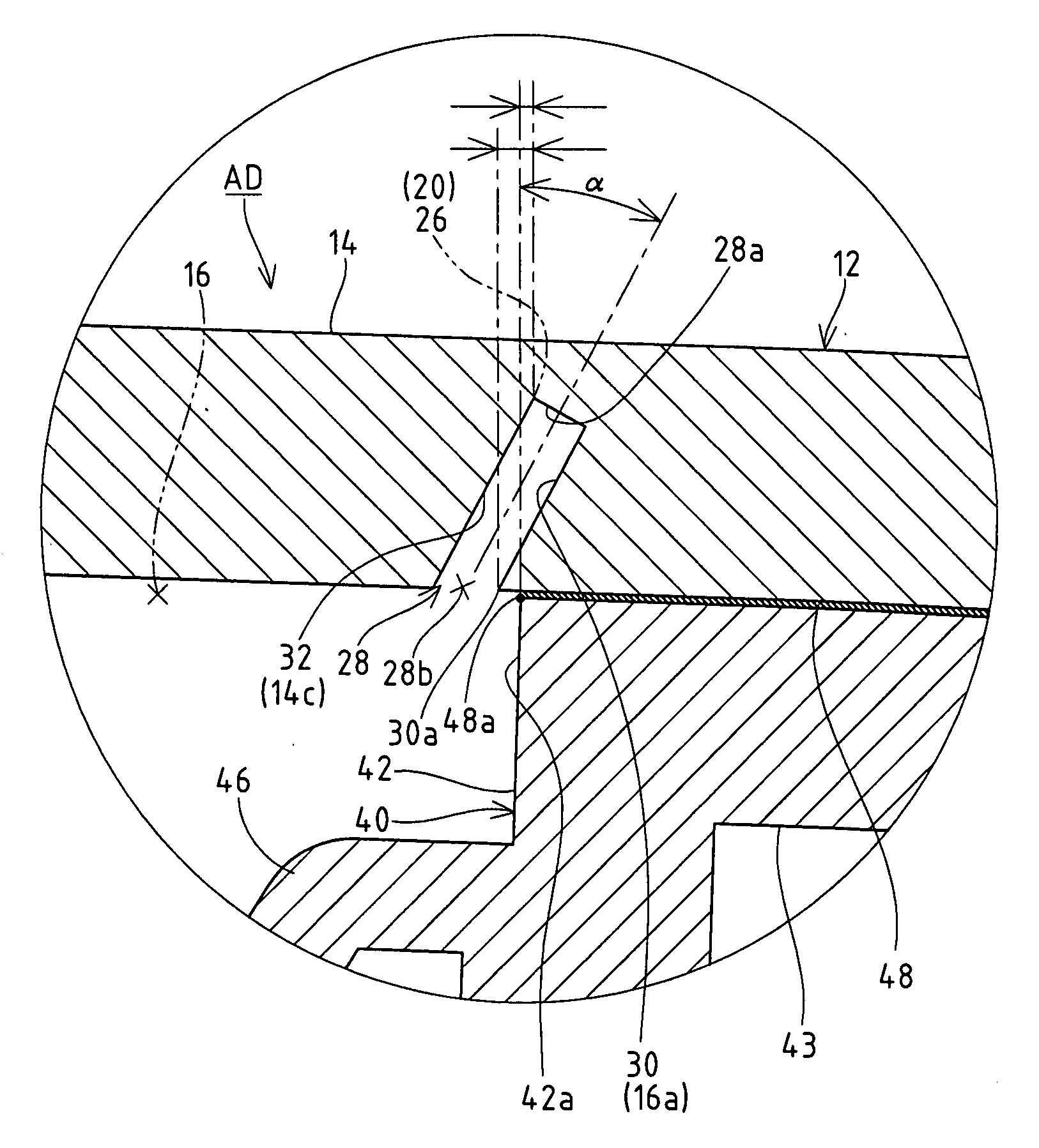
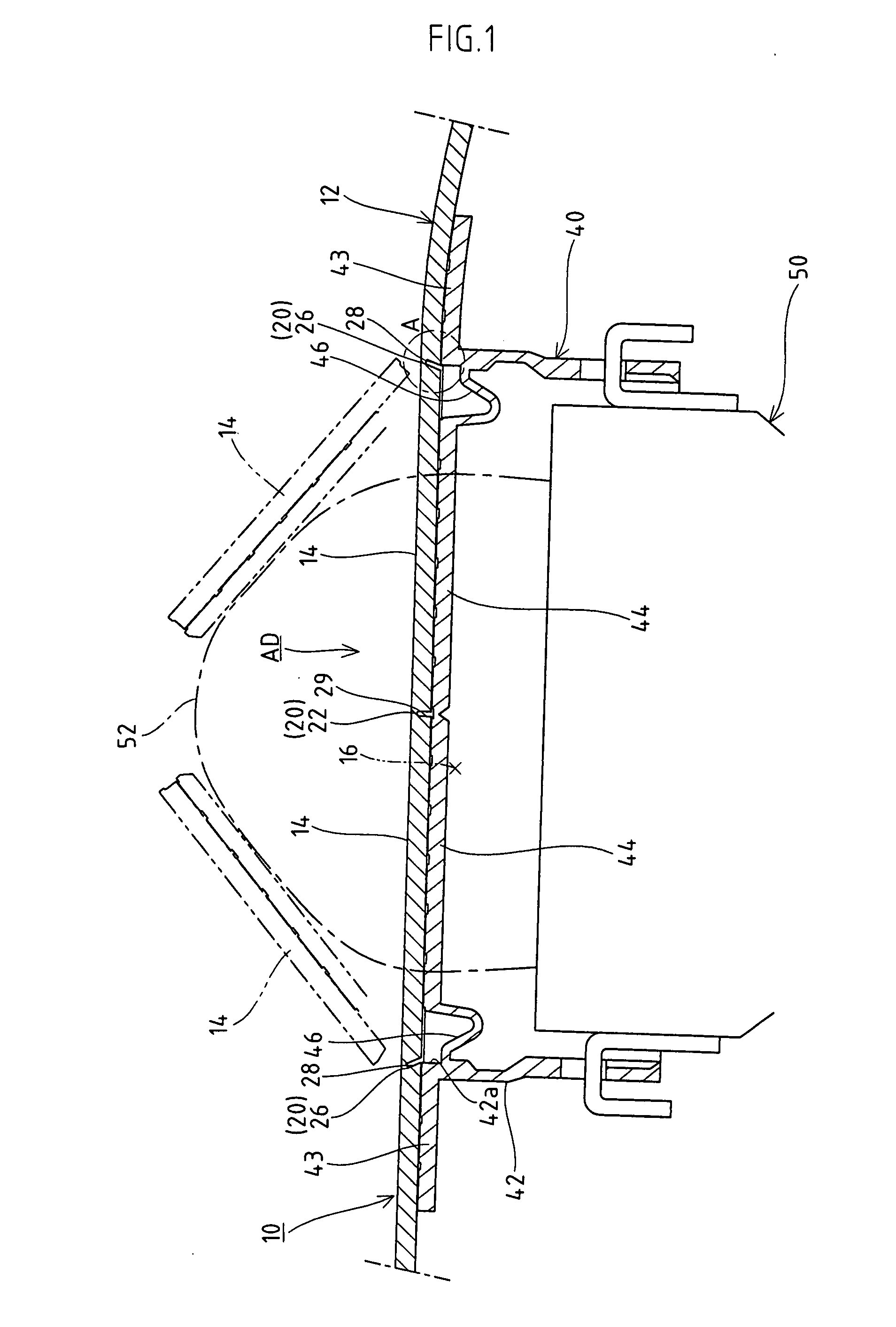
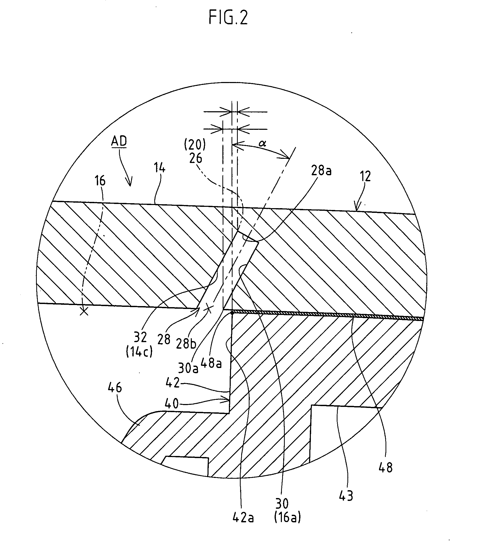
[0032]FIG. 1 shows an air bag door AD provided at an instrument panel 10 which is an interior part for a vehicle. The air bag door AD is a double-swing type having two door panels 14, 14 integrally formed at a base 12, and constitutes a part of the base 12. When an air bag apparatus 50 of the air bag door AD is activated to inflate an air bag 52, the pressure generated then breaks a predetermined break portion 20 provided at the base 12, the door panels 14, 14 are opened away from each other about respective proximal-end edges 14c (see FIG. 1 or FIG. 3). Groove portions 28, 29 which form the predetermined break portion 20 are open to the back side of the base 12 so that the predetermined break portion 20 cannot be seen from the cabin side facing the designed surface (face side).

[0033]In the air bag door AD, the face side of the door panels 14, 14 and the back side of the periphery of the air bag opening 16 formed in the base 12 when the door panels 14, 14 are opened are supported in...


PUM


Abstract

An air bag door ensures smoother inflation of an air bag. The air bag door has a groove portion of a predetermined depth serving as a predetermined break portion and provided at the peripheral edge of a door panel provided at a base of an instrument panel. The first groove portion extending at the boundary between the base and the door panel has side wall surfaces defining the base side of the first groove portion. The side wall surfaces are obliquely formed in such a way as to come away outward from the door panel as the groove portion extends toward a bottom portion from an open end opening at the back side of the base. The predetermined break portion provided at the bottom portion of the first groove portion is positioned outward of a base-side corner portion of the open end.

Description

BACKGROUND OF THE INVENTION[0001]1. Field of the Invention[0002]The present invention relates to an air bag door, and, more particularly, to an air bag door having a groove portion of a predetermined depth serving as a predetermined break portion provided and extending at the peripheral edge of a door panel provided on a base of an interior part for a vehicle.[0003]2. Description of the Related Art[0004]A vehicle or the like is equipped with an air bag apparatus for protecting a passenger inside. As shown in FIG. 4, for example, an air bag apparatus 50 for a passenger seat is accommodated in an instrument panel (interior part for vehicle) 10 installed in the front part of a cabin. Therefore, door panels 14, 14 of an air bag door AD1 which opens toward the cabin are provided on a base 12, constituting the instrument panel 10, are formed at positions corresponding to the air bag apparatus 50.[0005]The door panels 14, 14 normally constitute the designed surface of the base 12 as a part...

Claims


Application Information

Patent Timeline
IPC IPC(8): B60R21/215B60R21/20B60R21/2165
CPCB60R2021/21537B60R21/2165
Inventor KAMIYA, KAZUNORI
Owner INOAC CORP
Why Eureka
Try Eureka