
Fluid ejection device and medical instrument

a technology of fluid ejection and medical instruments, which is applied in the direction of fluid jet surgical cutters, medical science, surgery, etc., can solve the problems of reducing the position accuracy of fluid ejection, affecting the operation efficiency of the surgical instrument, and the surgical target may be obscured from view, so as to achieve excellent characteristics of the surgical instrument

Active Publication Date: 2014-12-18
SEIKO EPSON CORP
View PDF8 Cites 1 Cited by
  • Summary
  • Abstract
  • Description
  • Claims
  • Application Information

AI Technical Summary

Benefits of technology

The design achieves increased positional accuracy and reduced noise during high-speed pulsed fluid ejection, while maintaining a simple structure and avoiding increased size and weight, thereby enhancing the device's maneuverability and surgical precision.

Problems solved by technology

During surgery, a surgery target may become obscured from view while using the fluid ejection device.
As a result, vibrations occur at the tip of the ejection tube when fluid is ejected in pulses at high speed.
Several problems arise from the vibrations that occur at the tip of the ejection tube.
For example, there is a decrease in the positional accuracy of the fluid ejection.
In addition, vibration noise is generated by the interference between the ejection tube and the suction tube into which the ejection tube is inserted.
However, this structure is complicated.
In addition, this structure deteriorates the maneuverability of the fluid ejection device due to the increased size and weight of the fluid ejection device resulting from this structure.
In this case, the tip of the ejection tube does not easily vibrate during high-speed ejection of pulsed fluid.
Furthermore, the suction opening having the substantially elliptic shape is not easily caught by the surgery target portion.

Method used


Image

  • Fluid ejection device and medical instrument
  • Fluid ejection device and medical instrument
  • Fluid ejection device and medical instrument

Examples


first embodiment

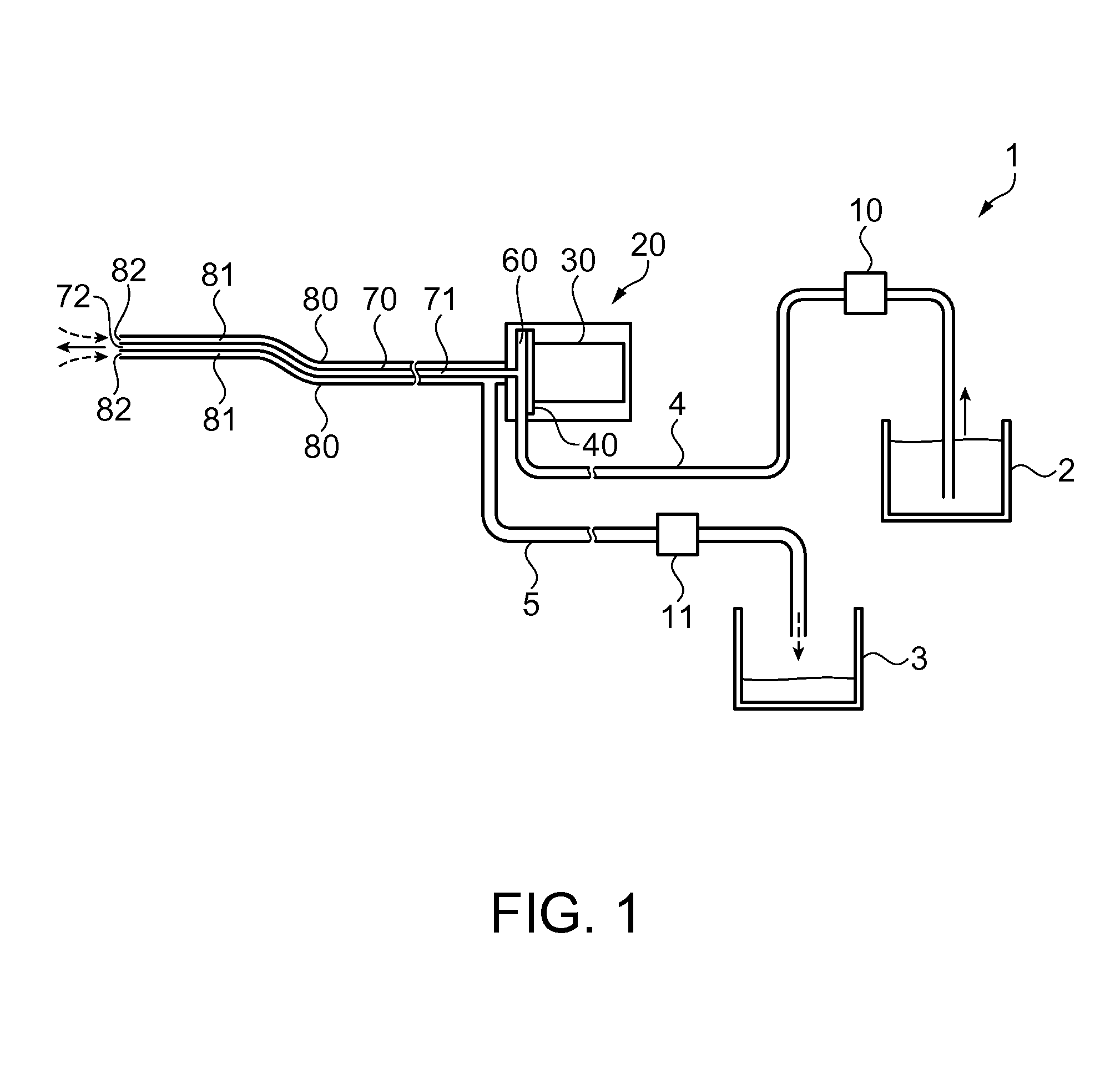
[0035]FIG. 1 illustrates a structure of a fluid ejection device according to a first embodiment. In this embodiment, a fluid ejection device included in a medical instrument will be discussed. The fluid ejection device in this embodiment includes, but is not limited to, functions such as excision, incision, exfoliation, and crushing. Further, the fluid ejection device is not limited to applications in the medical field.

[0036]As illustrated in FIG. 1, a fluid ejection device 1 includes a fluid supply container 2 storing fluid, a supply pump 10 as a fluid supply unit, a pulsation generator 20 which converts fluid supplied from the supply pump 10 into pulsed fluid, an ejection tube 70 which communicates with the pulsation generator 20, a suction tube 80 which extends from the pulsation generator 20, a suction pump 11 as a suction unit, and a waste fluid container 3 which stores sucked waste liquid and excised tissue. The pulsation generator 20, the supply pump 10, and the fluid supply ...

first example

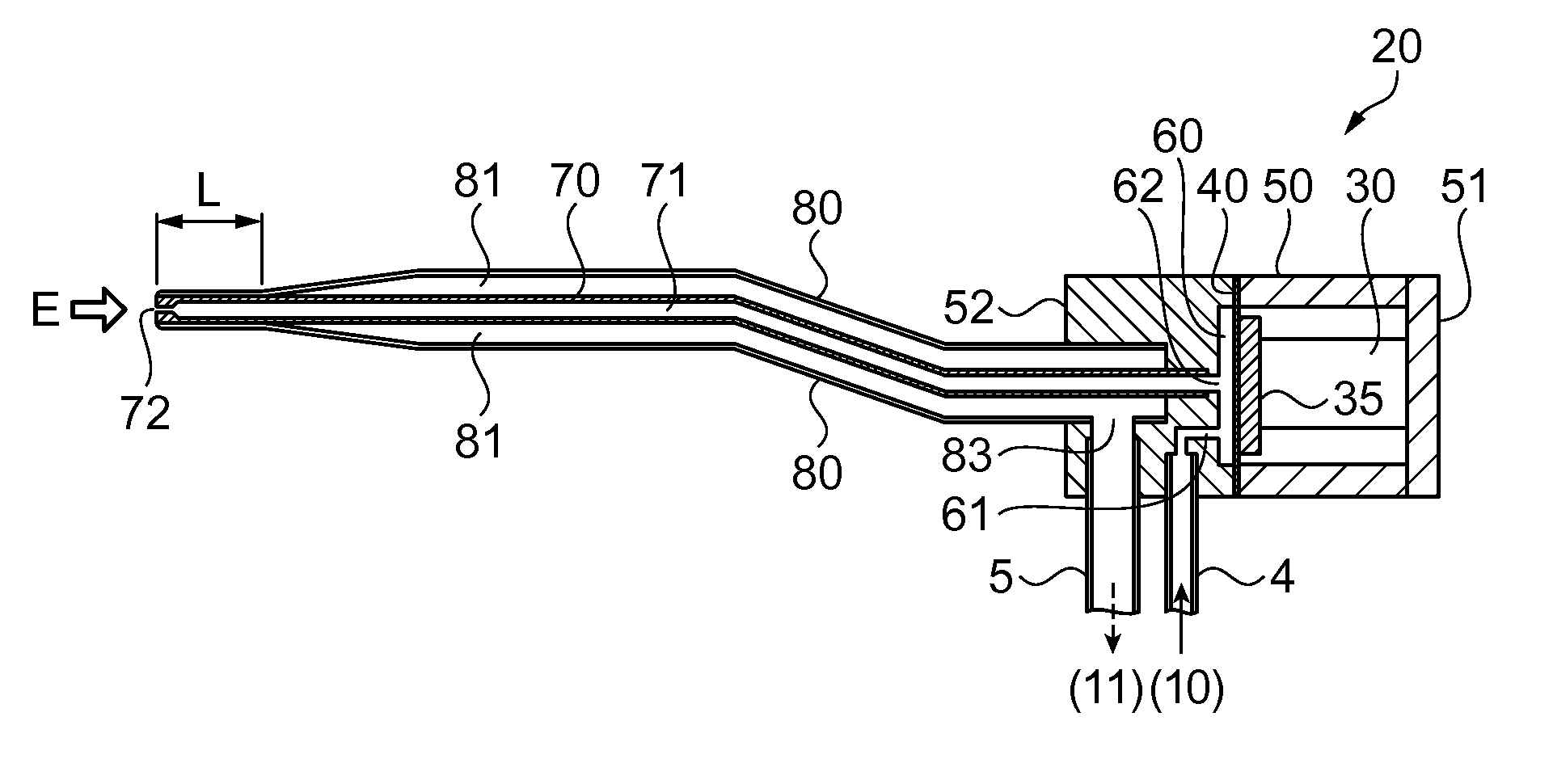
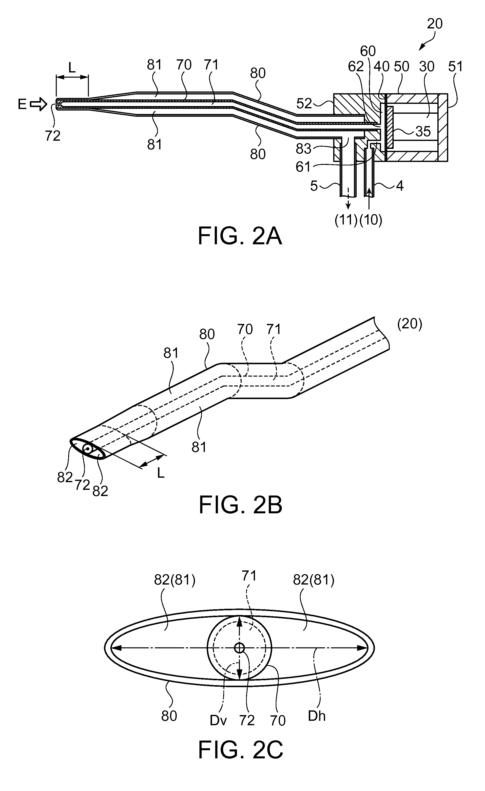
[0046]FIG. 2A is a side cross-sectional view of the pulsation generator, the ejection tube, and the suction tube according to the first example taken along a plane extending in the flow direction of the fluid. FIG. 2B is a perspective view illustrating a tip structure of the ejection tube and the suction tube. FIG. 2C is a front view illustrating example tips of the ejection tube and the suction tube as viewed from the tip direction (direction of E in FIG. 2A).

[0047]As illustrated in FIG. 2A, the pulsation generator 20 includes an inlet channel 61 through which fluid supplied from the supply pump 10 via the fluid supply channel tube 4 is introduced into the fluid chamber 60. The pulsation generator 20 also includes the piezoelectric device 30 and the diaphragm 40 as the volume varying unit for varying the volume of the fluid chamber 60, and an outlet channel 62 communicating with the fluid chamber 60.

[0048]The diaphragm 40 is formed by a disk-shaped metal thin plate in this example,...

second example

[0064]A second example is now described with reference to the drawings. FIG. 3A is a perspective view illustrating an example of a tip structure of the ejection tube and the suction tube according to the second example. FIG. 3B is a cross-sectional view taken along a line A-A in FIG. 3A. According to the first example, the suction tube 80 is constituted by a single piece structure. In this example, however, the tip portion of the suction tube 80 is a component that can be separated from the suction tube 80 and that engages with the suction tube 80 in such a manner as to be rotatable around the axis of the suction tube 80. Components and parts in this example which correspond to similar components and parts in the first example have been given similar reference numbers, and the same explanation is not repeated.

[0065]As illustrated in FIG. 3A, the suction tube 80 has a tip portion 80b, and a suction tube portion 80a extending between the pulsation generator 20 and the tip portion 80b....


PUM


Abstract

A fluid ejection device includes a pulsation generator which converts a fluid into a pulsed fluid, a fluid supply unit (supply pump) which supplies the fluid to the pulsation generator, an ejection tube which has an ejection opening communicating with the pulsation generator, a suction tube into which the ejection tube is inserted with play, a suction channel provided between the suction tube and the ejection tube, a suction opening provided at an end of the suction channel in a vicinity of the ejection opening, and a suction unit (suction pump) which sucks fluid in such a manner that the fluid introduced from the suction opening passes through the suction channel. The ejection opening is held by an inner circumferential part of the suction opening. According to this structure, vibration of the ejection tube in the vicinity of the ejection opening can be reduced.

Description

CROSS-REFERENCE TO RELATED APPLICATIONS[0001]The present application is a Continuation of U.S. patent application Ser. No. 13 / 269,885, filed on Oct. 10, 2011, which claims priority to Japanese Patent Application No: 2010-229325, filed Oct. 12, 2010, which applications are expressly incorporated by reference herein.BACKGROUND[0002]1. Technical Field[0003]Embodiments of the present invention relate to a fluid ejection device, and a medical instrument including the fluid ejection device.[0004]2. Related Art[0005]A fluid ejection device capable of excising, incising, and crushing living tissue has excellent characteristics when used as a surgical instrument. A low probability of heat damage and preservation of blood vessels including capillaries are examples of these characteristics.[0006]During surgery, a surgery target may become obscured from view while using the fluid ejection device. A certain type of fluid ejection device has a suction tube which sucks and removes the ejected liqu...

Claims


Application Information

Patent Timeline
Patent Type & Authority Applications(United States)
IPC IPC(8): A61B17/3203
CPCA61B2017/00154A61B17/3203A61B2217/005A61B2217/007
Inventor KOJIMA, HIDEKIHIRABAYASHI, ATSUYA
Owner SEIKO EPSON CORP
Learn More