Hydraulic detent for a variable camshaft timing device

a technology of variable camshaft timing and hydraulic detent, which is applied in the direction of valve arrangement, oscillating piston engines, machines/engines, etc., can solve problems such as unsatisfactory noise, and achieve the effect of facilitating the oscillation of the van

Inactive Publication Date: 2003-12-23
BORGWARNER INC
View PDF17 Cites 48 Cited by
  • Summary
  • Abstract
  • Description
  • Claims
  • Application Information

AI Technical Summary

Benefits of technology

In a VCT phaser a bi-directional or two bypass passage structure is provided to reach the "detent" position very rapidly from either direction.
Accordingly, a phaser which includes a housing and a rotor disposed to rotate relative to each other is provided. The housing has at least one cavity disposed to be divided by a vane rigidly attached to the rotor. The vane divides the cavity into a first chamber and a second chamber. The phaser further includes passages connecting the first and the second chamber, thereby facilitating the oscillation of the vane within the cavity. The phaser comprises: a) a valve disposed to form at least two openings for fluid flowing between the first chamber and the second chamber and being disposed to keep at least one opening closed; and b) at least one by-pass disposed to stop or slow down the rotation between the housing and the rotor, thereby allowing a locking mechanism to lock the housing and the rotor together independent of fluid flow.
Accordingly, a phaser which includes a housing and a rotor disposed to rotate relative to each other is provided. The housing has at least one cavity disposed to be divided by a vane rigidly attached to the rotor. The vane divides the cavity into a first chamber and a second chamber. The phaser further includes passages connecting the first and the second chamber, thereby facilitating the oscillation of the vane within the cavity. A method is provided which includes the steps of: a) providing a valve disposed to form at least two openings for fluid flowing between the first chamber and the second chamber and being disposed to keep at least one opening closed; and b) providing at least one bypass disposed to stop or slow down the rotation between the housing and the rotor, thereby allowing a locking mechanism to lock the housing and the rotor together independent of fluid flow.

Problems solved by technology

This touching or stoppage causes undesirable noise.

Method used


Image

  • Hydraulic detent for a variable camshaft timing device
  • Hydraulic detent for a variable camshaft timing device
  • Hydraulic detent for a variable camshaft timing device

Examples


Embodiment Construction

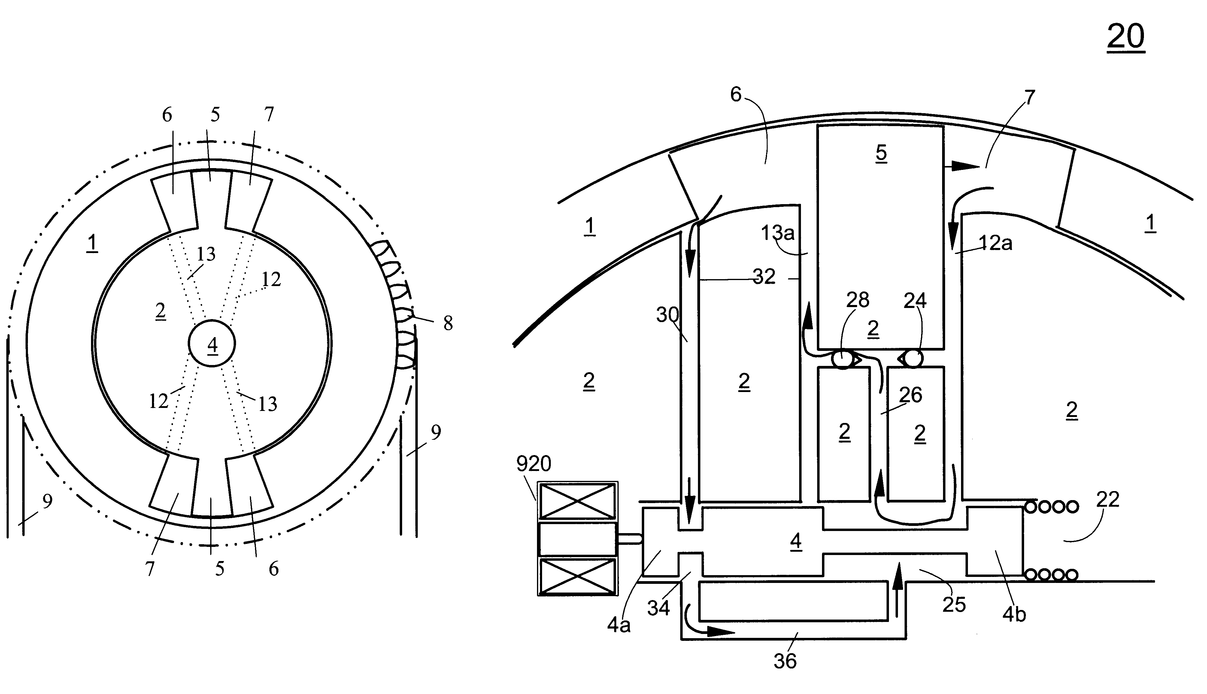
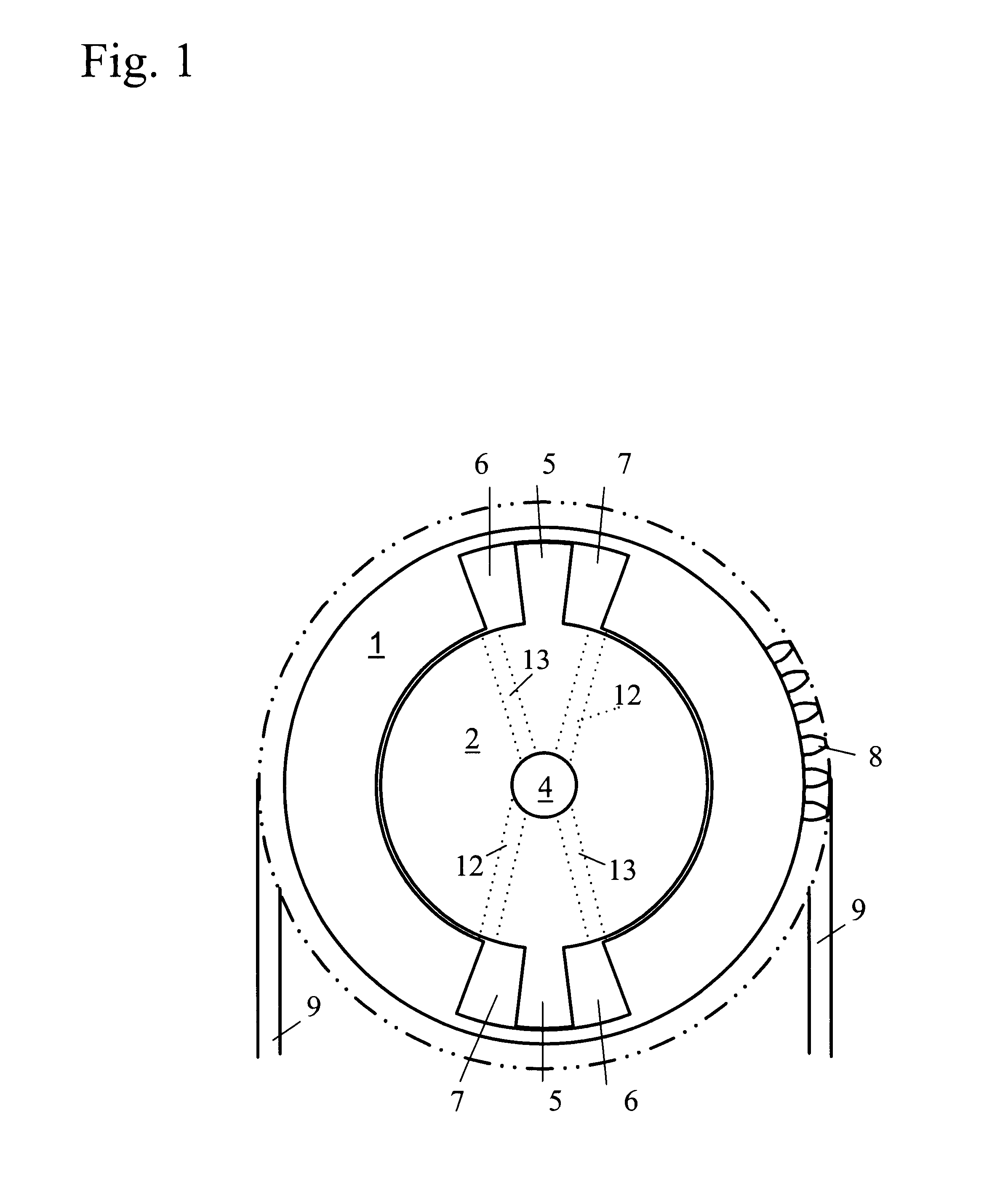
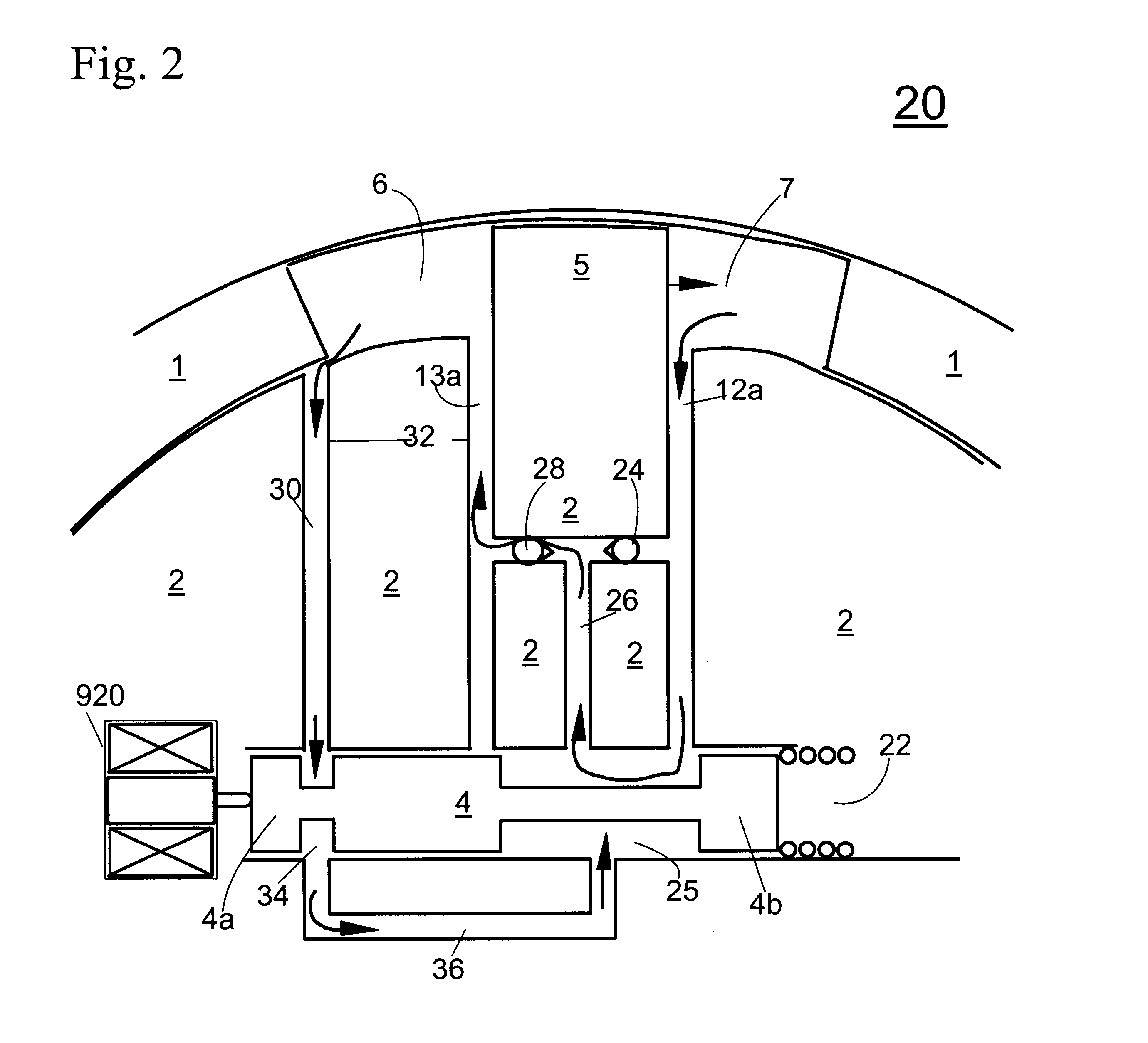
Referring to FIG. 1, a vane-type VCT phaser comprises a housing (1), the outside of which has sprocket teeth (8) which mesh with and are driven by timing chain (9). Inside the housing (1), a cavity including fluid chambers (6) and (7) is defined. Coaxially within the housing (1), free to rotate relative to the housing, is a rotor (2) with vanes (5) which fit between the chambers (6) and (7), and a central control valve (4) which routes pressurized oil via passages (12) and (13) to chambers (6) and (7), respectively. Pressurized oil introduced by valve (4) into passages (12) will push vanes (5) counterclockwise relative to the housing (1), forcing oil out of chambers (6) into passages (13) and into valve (4). It will be recognized by one skilled in the art that this description is common to vane phasers in general, and the specific arrangement of vanes, chambers, passages and valves shown in FIG. 1 may be varied within the teachings of the invention. For example, the number of vanes ...


PUM


Abstract

A phaser which includes a housing and a rotor disposed to rotate relative to each other is provided. The housing has at least one cavity disposed to be divided by a vane rigidly attached to the rotor. The vane divides the cavity into a first chamber and a second chamber. The phaser further includes passages connecting the first and the second chamber, thereby facilitating the oscillation of the vane within the cavity. The phaser includes: a) a valve disposed to form at least two openings for fluid flowing between the first chamber and the second chamber and being disposed to keep at least one opening closed; and b) at least one by-pass disposed to stop or slow down the rotation between the housing and the rotor, thereby allowing a locking mechanism to lock the housing and the rotor together independent of fluid flow.

Description

BACKGROUND OF THE INVENTION1. Field of the InventionThe invention pertains to the field of variable camshaft timing (VCT) devices. More particularly, the invention pertains to a Hydraulic Detent for a Variable Camshaft Timing device, in which the hydraulic detent reduces noise by forming a bypass.2. Description of Related ArtThe performance of an internal combustion engine can be improved by the use of dual camshafts, one to operate the intake valves of the various cylinders of the engine and the other to operate the exhaust valves. Typically, one of such camshafts is driven by the crankshaft of the engine, through a sprocket and chain drive or a belt drive, and the other of such camshafts is driven by the first, through a second sprocket and chain drive or a second belt drive. Alternatively, both of the camshafts can be driven by a single crankshaft powered chain drive or belt drive. Engine performance in an engine with dual camshafts can be further improved, in terms of idle quali...

Claims


Application Information

Patent Timeline
Patent Type & Authority Patents(United States)
IPC IPC(8): F01L1/344F01L1/34F15B15/12
CPCF01L1/34F15B15/12F01L1/344F01L1/3442F01L2001/3443F01L2001/34433F01L2810/04
Inventor SMITH, FRANKLIN R.WING, BRAMAN
Owner BORGWARNER INC
Why Eureka
Try Eureka