Ultrasonic transducer and signal decay time adjusting method applied thereto

Inactive Publication Date: 2011-02-03
LITE ON IT
View PDF11 Cites 20 Cited by
  • Summary
  • Abstract
  • Description
  • Claims
  • Application Information

AI Technical Summary

Benefits of technology

[0012]In accordance with another aspect of the present invention, there is provided an ultrasonic transducer having a function of adjusting a signal decay time. The ultrasonic transducer includes a pre-processing module and an ultrasonic transmitting/receiving module. The pre-processing module is used for generating a first driving signal, and generating a second driving signal according to the first driving signal after the first driving signal is stopped. The ultrasonic transmitting/receiving module is in communication with the pre-processing module for receiving the first driving signal, and generati

Problems solved by technology

If the distance between the ultrasonic transducer and the object is too short, the waveform or decay signal resulted from the ringing phenomenon has adverse influences on the performance of receiving the reflective wave.
On the other hand, if the distance of the object from the

Method used


Image

  • Ultrasonic transducer and signal decay time adjusting method applied thereto
  • Ultrasonic transducer and signal decay time adjusting method applied thereto
  • Ultrasonic transducer and signal decay time adjusting method applied thereto

Examples


Embodiment Construction

[0021]The present invention will now be described more specifically with reference to the following embodiments. It is to be noted that the following descriptions of preferred embodiments of this invention are presented herein for purpose of illustration and description only. It is not intended to be exhaustive or to be limited to the precise form disclosed.

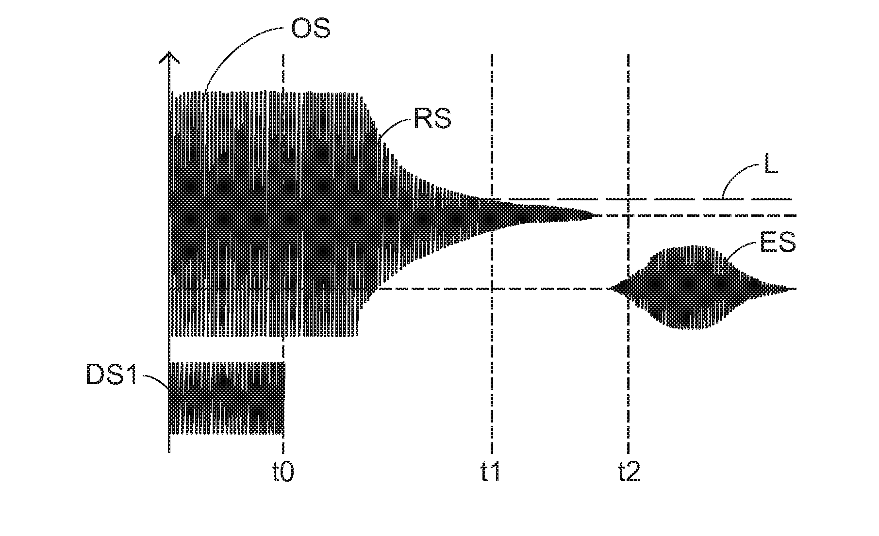
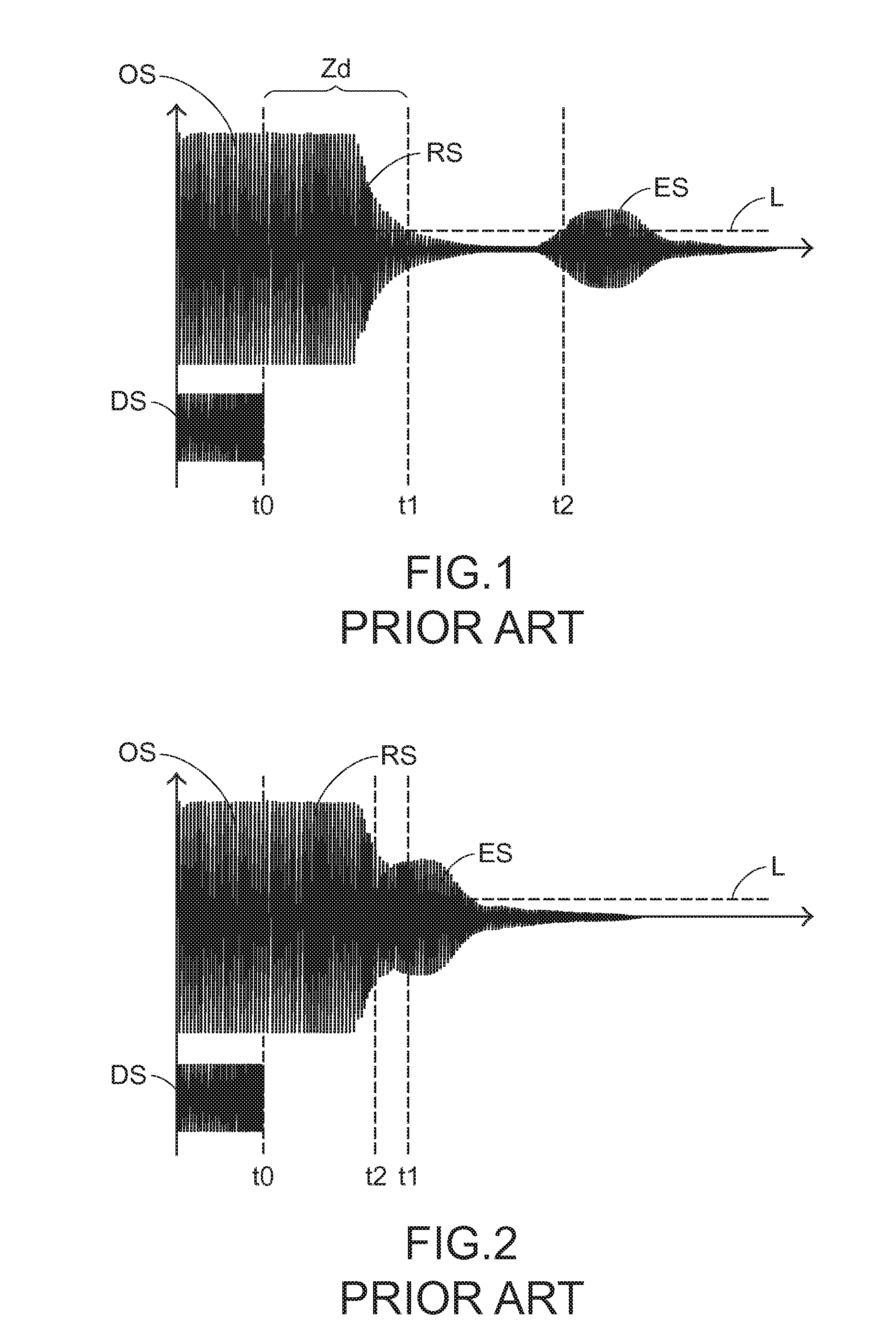
[0022]As previously described, the piezoelectric film within the ultrasonic transducer generates corresponding vibration and transmits a sensing wave. When the driving signal is stopped, the waveform of the decay signal has a dead zone, which is detrimental for processing and receiving the echo signal. The influence on the performance of processing and receiving the echo signal is dependent on the length of the dead zone. As the dead zone is widened, the scope of application of the ultrasonic transducer is reduced. If the dead zone is zero, even a nearby object can be detected by the ultrasonic transducer. In other words, the dec...


PUM


Abstract

A signal decay time adjusting method is used in an ultrasonic transducer. Firstly, a first driving signal is generated by a pre-processing module. When the first driving signal is received, an ultrasonic transmitting/receiving module generates vibration and transmits a sensing wave according to the first driving signal. Then, the pre-processing module stops generating the first driving signal so that the vibration generated within the ultrasonic transmitting/receiving module is decayed as a decay signal. Then, a second driving signal is generated by the pre-processing module according to the first driving signal, and the second driving signal is transmitted to the ultrasonic transmitting/receiving module. When the second driving signal is received, the decay signal is offset according to the second driving signal, so that a decay time of the decay signal is shortened. When the sensing wave is reflected by an object, a reflective wave is received by the ultrasonic transmitting/receiving module.

Description

FIELD OF THE INVENTION[0001]The present invention relates to an ultrasonic transducer, and more particularly to an ultrasonic transducer having a function of adjusting a signal decay time. The present invention also relates to signal decay time adjusting method applied to the ultrasonic transducer. By adjusting the phase, amplitude, pulse number and frequency of a driving signal, the decay time of a decay signal generated within the ultrasonic transducer is quickly reduced.BACKGROUND OF THE INVENTION[0002]An ultrasonic transducer is a device that converts energy into ultrasonic waves. A conventional ultrasonic transducer is used for generating single-frequency ultrasonic waves. Another type of ultrasonic transducer contains two independently operated elements in a single housing, wherein one of the elements is a transmitter, and the other is a receiver. That is, a transmitter and a receiver are included in the ultrasonic transducer. The transmitter and the receiver face the same sid...

Claims


Application Information

Patent Timeline
IPC IPC(8): G01S7/524G01S7/527
CPCG01S7/527G01S7/524
Inventor BECKHOVEN, STEEF VANKALFS, JOHANKLEIN SWORMINK, MICHELCHEN, HANTINGLIAO, SIAN-CING
Owner LITE ON IT
Why Eureka
Try Eureka