Security system and method

a security system and security technology, applied in the field of security systems, can solve the problems of limited success, limited manpower for protecting all the border lines, and limited long-range surveillance means such as radar or airborne reconnaissance, and achieve the effects of fast response capability, fast detection capability, and rapid access to any remote location

Inactive Publication Date: 2006-02-23
AVNERI SHAHAR
View PDF3 Cites 22 Cited by
  • Summary
  • Abstract
  • Description
  • Claims
  • Application Information

AI Technical Summary

Benefits of technology

[0017] Thus, the new patrol system can provide both a fast detection capability and a fast response capability. These benefits are achieved in an unmanned system, without unnecessarily exposing patrols to unexpected attacks. The system can operate day and night, in adverse weather, to quickly reach any remote location.
[0018] The rail can be installed in such a way as to adapt to the terrain characteristics and tactical requirements, for example to allow the surveillance of canyons and valleys. This structure enables the patrol devices to climb up hills and scan areas that may be inaccessible to motorized forces or foot soldiers or guards.

Problems solved by technology

At present, despite the investments being made in manpower, equipment and other means for the protection of long borders or an area's perimeter, only a limited measure of success has been achieved.
As the borders are exposed to many penetration and / or attack attempts, a significant part of these attempts may succeed, with disastrous results.
It may be impossible, or very expensive, to allocate manpower for protecting all the border line, all the time.
Moreover, long range surveillance means such as radar or airborne reconnaissance may be limited by terrain obstructions or weather conditions.
Thus, at night, in bad weather, in hilly terrain, it may be difficult to protect border areas.
A problem with this practice is that the border patrol forces themselves are convenient targets for the enemy.
A further problem is that, by learning the routine of the guards, potential intruders may determine the opportune time for infiltrating the protected area, unhindered.
Moreover, the effectiveness of the patrol forces is limited by fatigue, adverse weather, low visibility and impassable terrain conditions.
Where weapons in a patrol unit are remotely controlled and activated, there is the danger of firing at civilians.

Method used


Image

  • Security system and method
  • Security system and method
  • Security system and method

Examples


Embodiment Construction

[0045] A preferred embodiment of the present invention will now be described by way of example and with reference to the accompanying drawings.

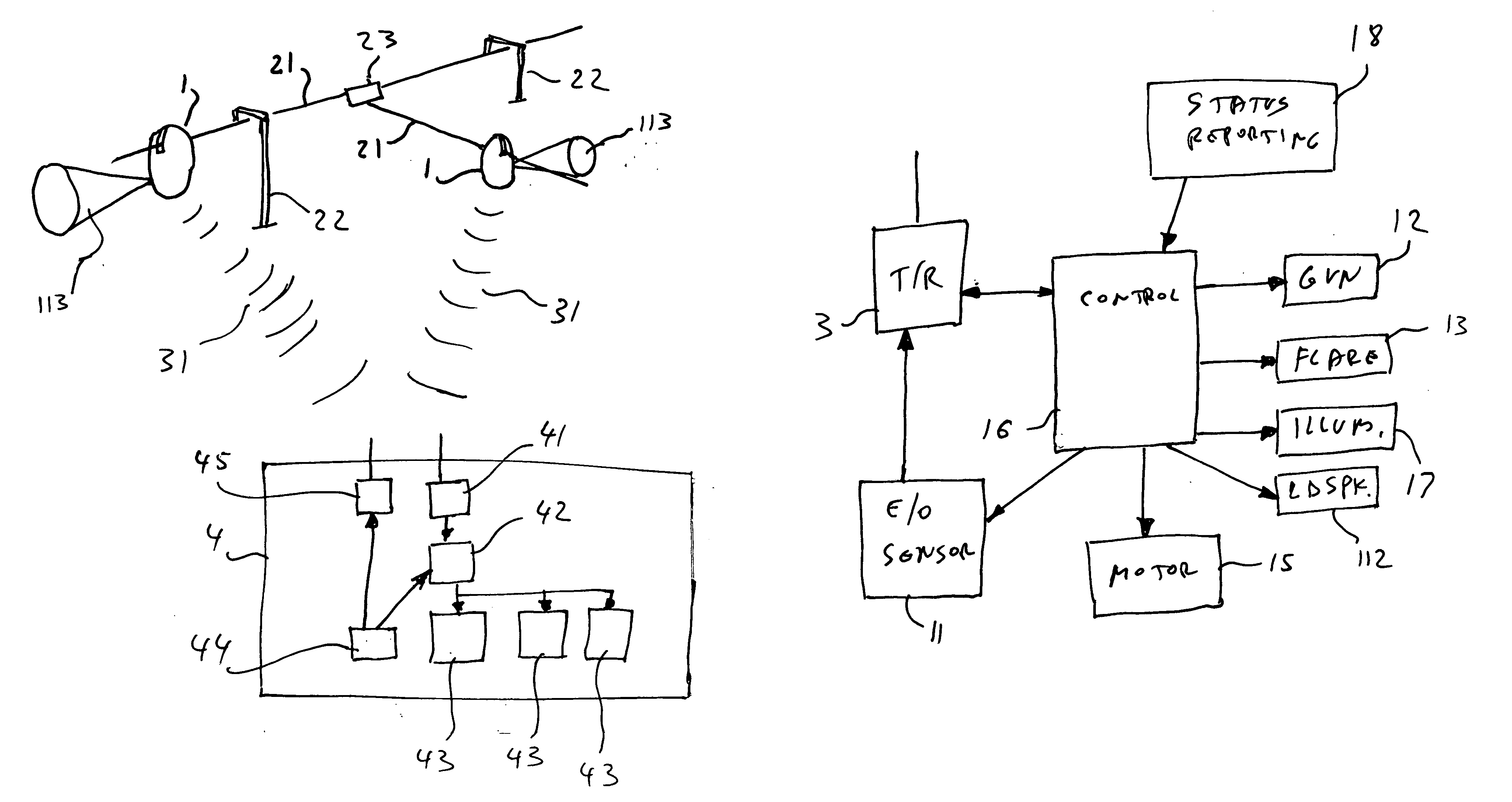
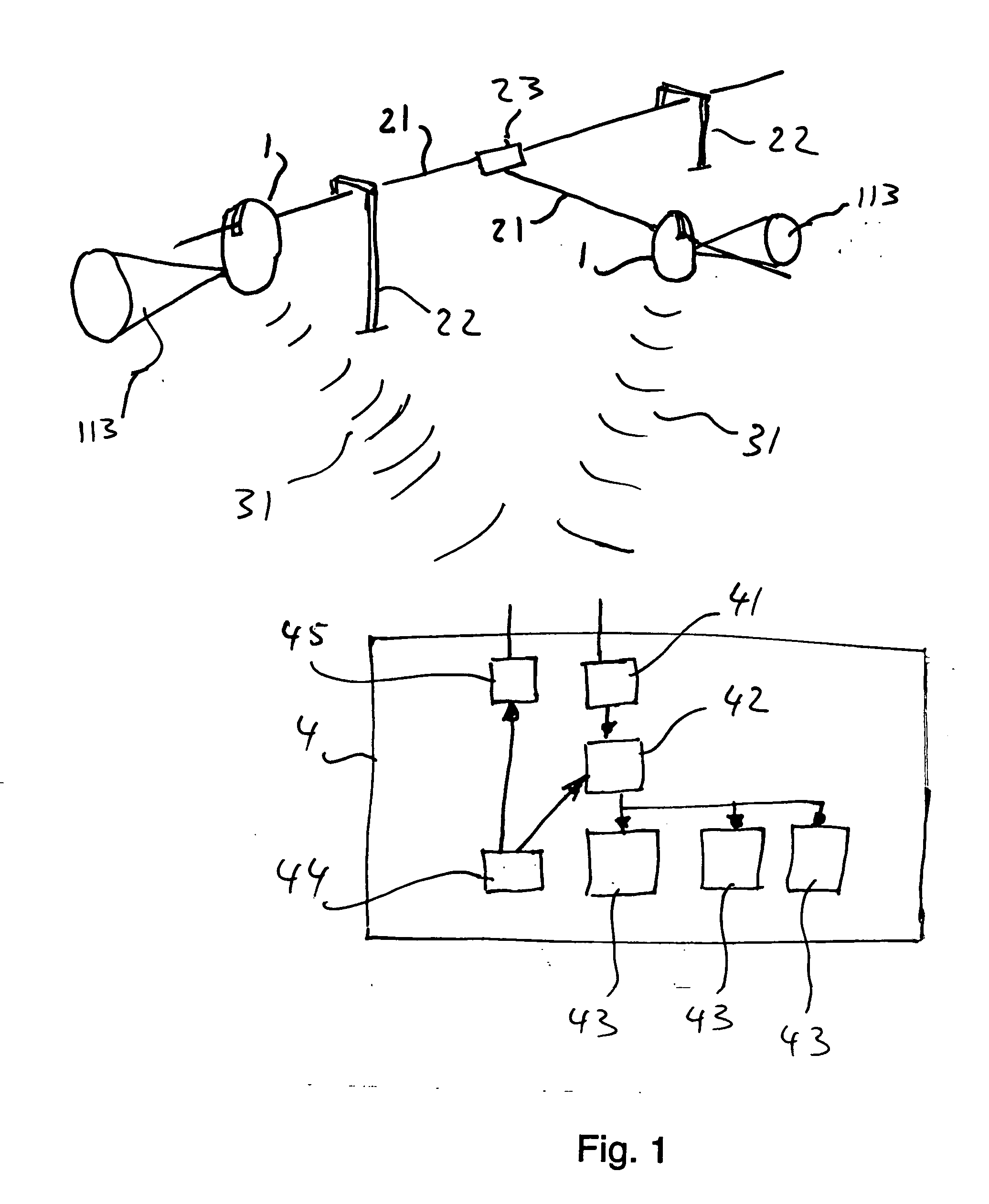
[0046]FIG. 1 illustrates a patrol and security system including patrol carriages 1 sliding on rails 21, supported by pylons 22. A plurality of rails 21 may be installed, with rails intersection means 23 therebetween.

[0047] Such a plurality of rails 21 and intersections 23 may facilitate the carriage movement along any of several paths, to cover a wider area, and to allow two units, which are traveling on the same rail in opposite directions, to pass over one another.

[0048] The actual carriage movement may be controlled by a control center, as detailed elsewhere in the present application. For example, the patrol carriages may alternately move along different rails, with several rails running in parallel at different heights, for irregular patrols and to confuse the enemy.

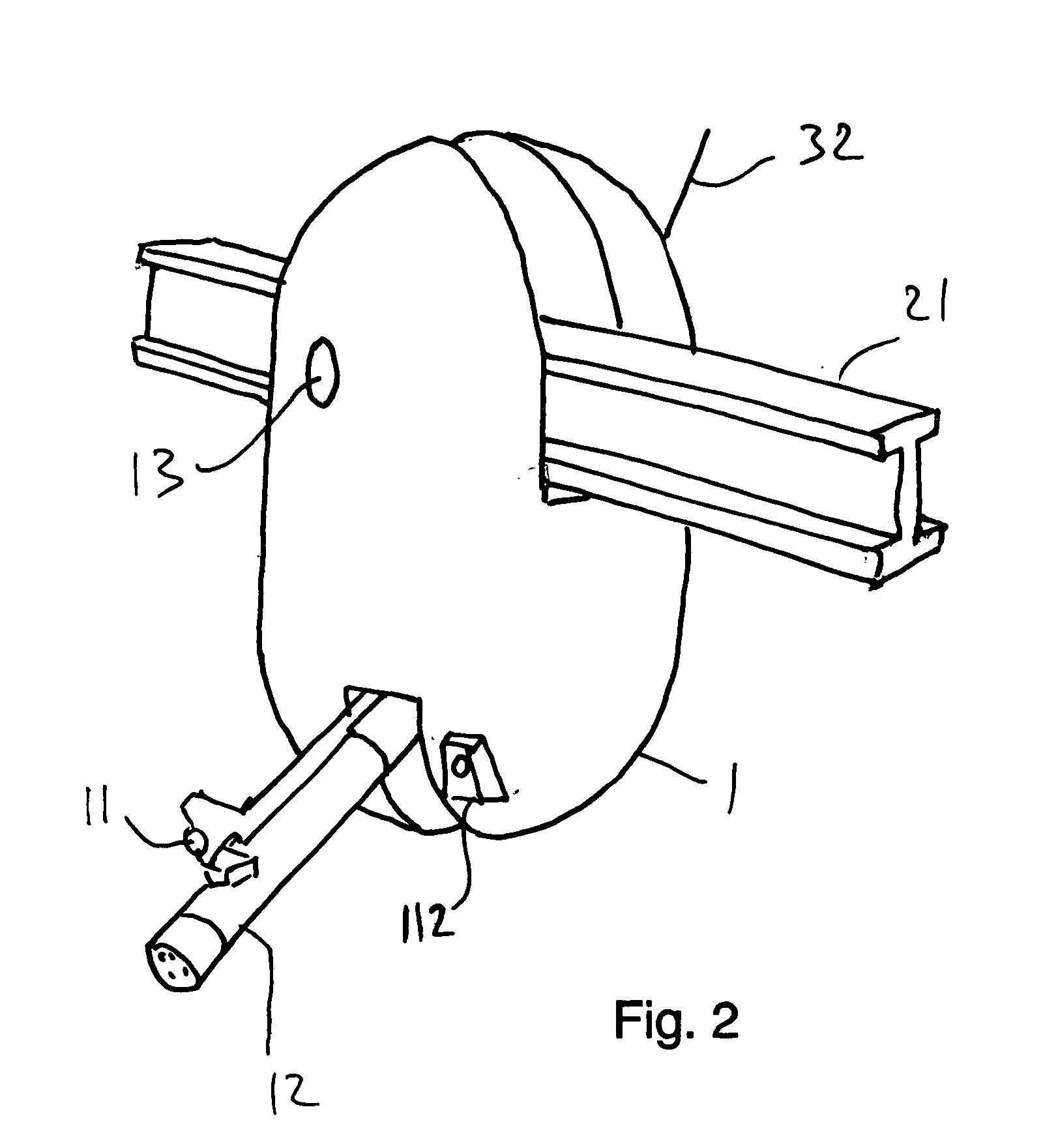
[0049] The carriages may include stabilization wheels, as detailed b...


PUM


Abstract

A patrol system comprising a carriage moving along guiding means. The carriage includes propulsion means, sensors for acquiring data from outside the carriage and control means. An automatic safety method comprising A. storing a digital map of safety zones in a computer; B. keeping track in real time of the carriage location and the area pointed at by the weapon; C. when a weapon activation command is issued, checking whether the intended attack will be pointed towards one of the safety zones; D. if the answer in step C is negative, then activating the weapon; if the answer is positive, then shooting will not be allowed.

Description

TECHNICAL FIELD [0001] The present invention claims priority from patent application 150123 filed in Israel on 10 Jun. 2002 and patent application PCT / IL03 / 00484 filed with RO / Israel on 9 Jun. 2003, wherein the latter application (PCT) claims priority from the former (Israel). This invention concerns security systems. The invention relates in particular to such systems comprising a plurality of carriages on rails for unmanned patrols along fences or borders.BACKGROUND ART [0002] At present, despite the investments being made in manpower, equipment and other means for the protection of long borders or an area's perimeter, only a limited measure of success has been achieved. As the borders are exposed to many penetration and / or attack attempts, a significant part of these attempts may succeed, with disastrous results. [0003] It may be impossible, or very expensive, to allocate manpower for protecting all the border line, all the time. Moreover, long range surveillance means such as ra...

Claims


Application Information

Patent Timeline
Patent Type & Authority Applications(United States)
IPC IPC(8): G08B13/00B61B3/00B60RB61B3/02B61B7/06B64D1/04G08BG08B13/196
CPCB61B3/02G08B13/19623B61B7/06
Inventor AVNERI, SHAHAR
Owner AVNERI SHAHAR
Why Eureka
Try Eureka