
Linear vibrator

a linear and vibrator technology, applied in the field of linear vibrators, can solve the problems of limiting vibration and difficult to increase vibration, and achieve the effect of improving the structure of the magnet and increasing vibration

Inactive Publication Date: 2015-03-24
EM TECHNOLOGY CO LTD
View PDF8 Cites 45 Cited by
  • Summary
  • Abstract
  • Description
  • Claims
  • Application Information

AI Technical Summary

Benefits of technology

[0010]Accordingly, the present invention provides a linear vibrator, which improves the structure of a magnet and a coil corresponding to the magnet so as to increase vibrations.

Problems solved by technology

However, the weight limits areas of a magnet and a coil, thus limiting vibrations.
However, the simple increase in size of the magnet does not positively affect the increase in vibrations.
When the size of the coil increases, a portion of the coil which does not generate electromagnetic force is also increased, so that it is difficult to increase vibrations.

Method used


Image

  • Linear vibrator
  • Linear vibrator
  • Linear vibrator

Examples


Embodiment Construction

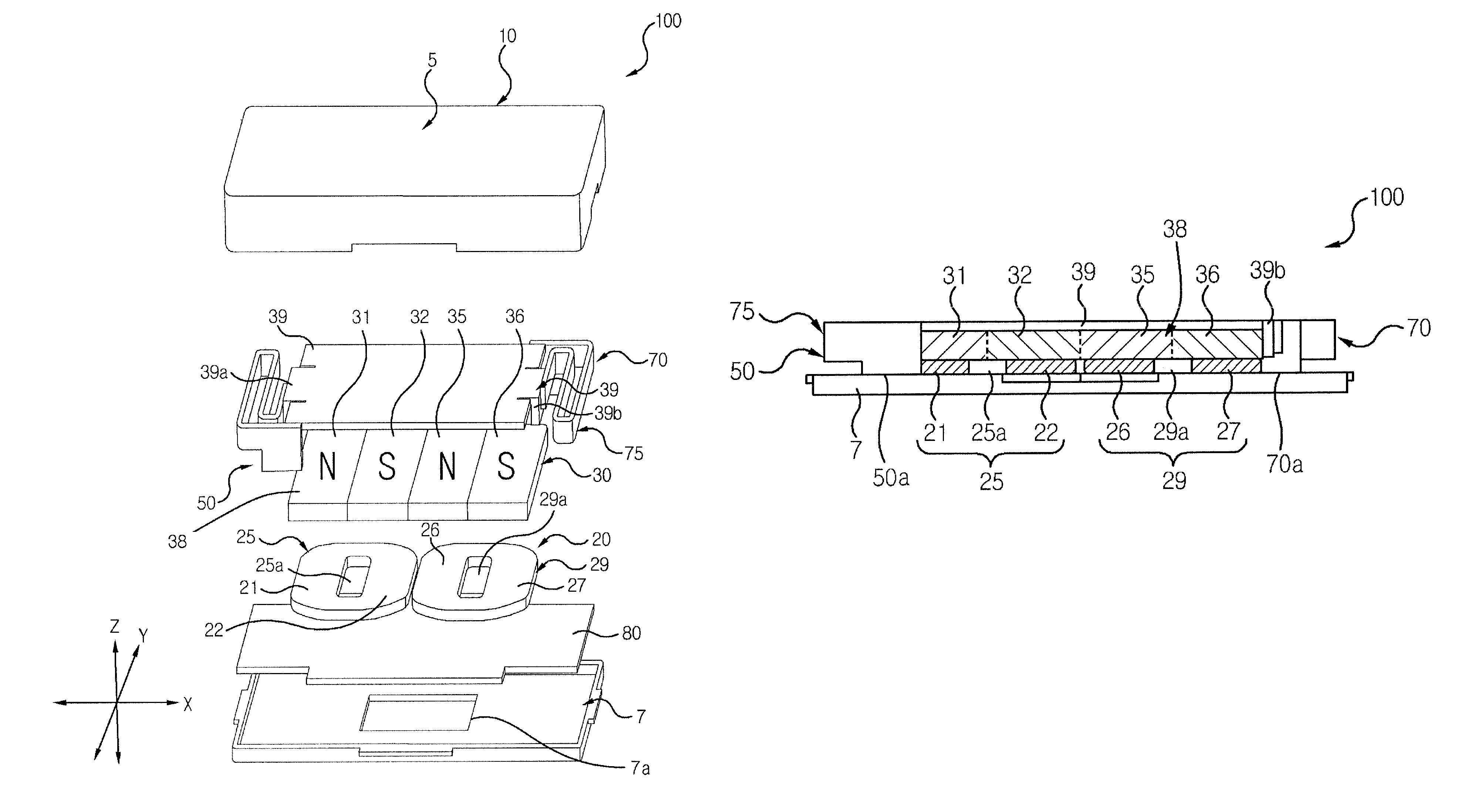
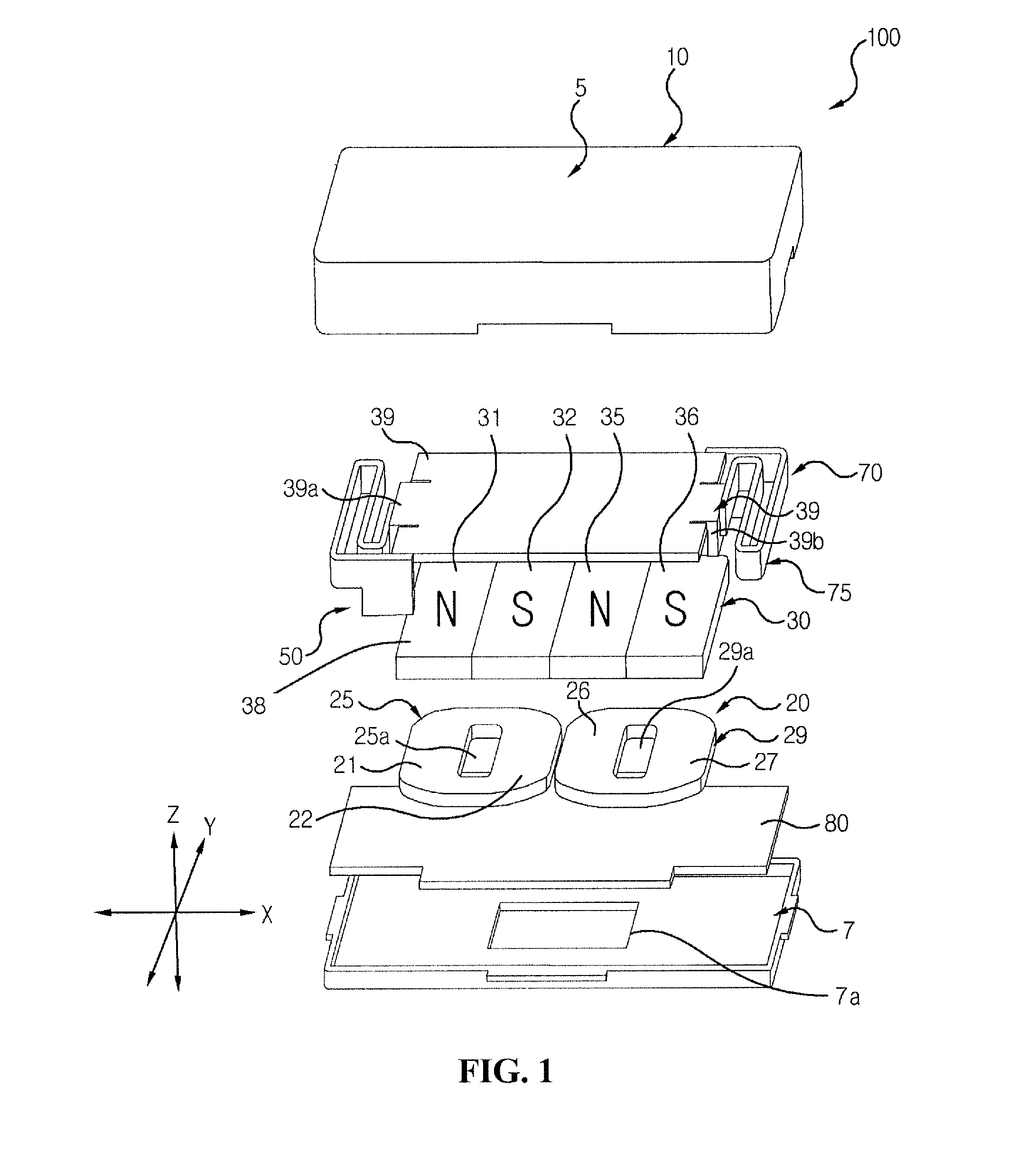
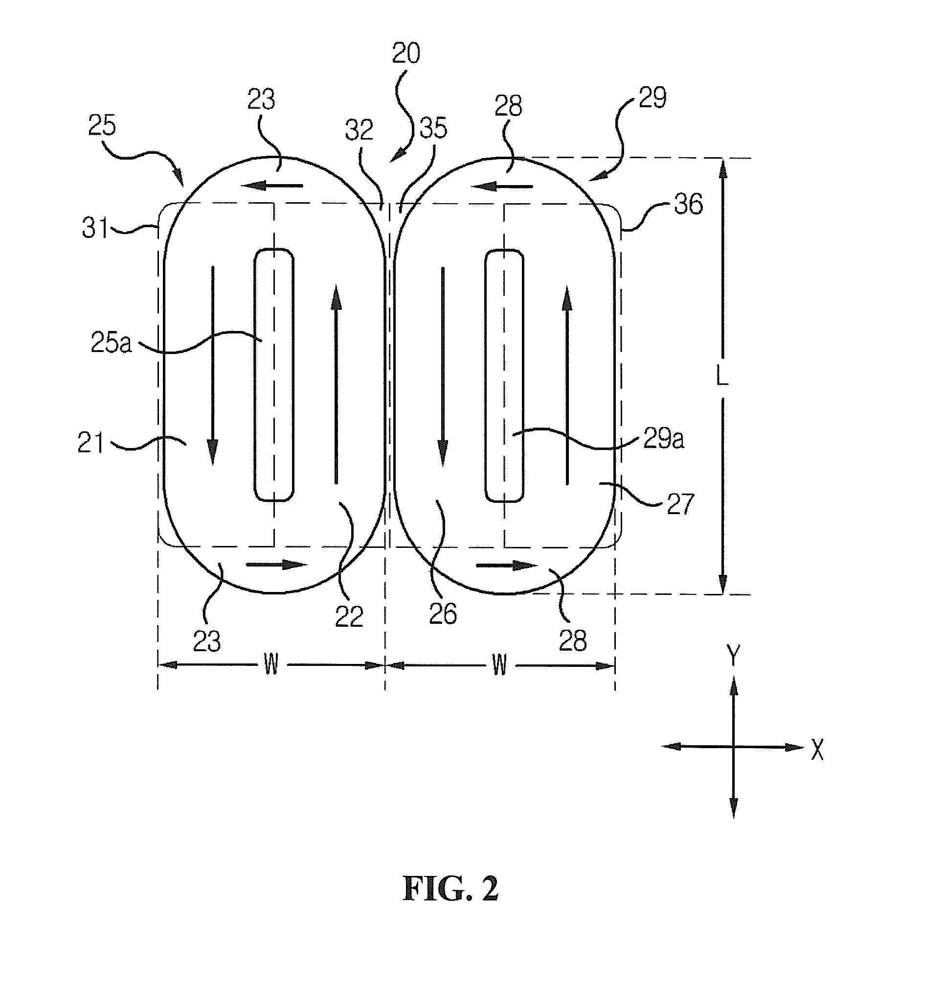
[0015]FIG. 1 is an exploded perspective view showing a linear vibrator in accordance with an exemplary embodiment of the present invention. FIG. 2 is a plan view showing a magnet and first and second coil blocks of the linear vibrator of FIG. 1. FIG. 3 is a side view showing the assembled state of the linear vibrator illustrated in FIG. 1.

[0016]Referring to FIGS. 1 to 3, a linear vibrator 100 includes a casing 10, a stator 20, a vibrator 30 and elastic members 75. In addition to these components, the linear vibrator 100 may further include a circuit board 80. The circuit board 80 is electrically connected to the stator 20.

[0017]The casing 10 includes an upper casing 5 and a lower casing 7. The casing 10 functions to receive and hold the stator 20, the vibrator 30 and the elastic members 75 that will be described below in detail.

[0018]The upper casing 5 has the shape of a rectangular parallelepiped box that is open at a bottom thereof, for example. The upper casing 5 may be formed by...


PUM


Abstract

Disclosed is a linear vibrator, the linear vibrator including a stator having first and second coil blocks coupled to a bottom plate of a casing, a vibrator having a magnet disposed at a position corresponding to the first and second coil blocks, and an elastic member elastically supporting the magnet.

Description

CROSS-REFERENCE TO RELATED APPLICATION[0001]This present application claims the benefit under 35 U.S.C. §119 of Korean Patent Application No. 10-2010-0105199, filed Oct. 27, 2010, which is hereby incorporated by reference in its entirety.BACKGROUND OF THE INVENTION[0002]1. Field of the Invention[0003]The present invention relates to a linear vibrator.[0004]2. Description of the Related Art[0005]Recently, small electronic products, such as mobile communication equipment, portable game machines, portable MP3 players and small home game machines, have been developed. The above-mentioned small electronic products include a display unit for transmitting data in the form of an image, and a sound unit for transmitting data in the form of voice. In recent, vibration motors that transmit data using vibrations have been mounted to the small electronic products.[0006]The vibration motors mounted on the small electronic products require the function of generating strong vibrations as well as sm...

Claims


Application Information

Patent Timeline
Patent Type & Authority Patents(United States)
IPC IPC(8): H02K33/16
CPCH02K33/16
Inventor PARK, YOUNGIL
Owner EM TECHNOLOGY CO LTD
Learn More