Hybrid crane mat with lifting elements
What is Al technical title?
Al technical title is built by PatSnap Al team. It summarizes the technical point description of the patent document.
a crane mat and lifting element technology, applied in the field of new hybrid crane mats, can solve the problems of inadvertent entry of workers into the lifting and movement of such mats, and achieve the effects of promoting safety for workers, improving properties, and reducing profil
Active Publication Date: 2018-01-09
QUALITY MAT
View PDF106 Cites 1 Cited by
Summary
Abstract
Description
Claims
Application Information
AI Technical Summary
This helps you quickly interpret patents by identifying the three key elements:
Problems solved by technology
Method used
Benefits of technology
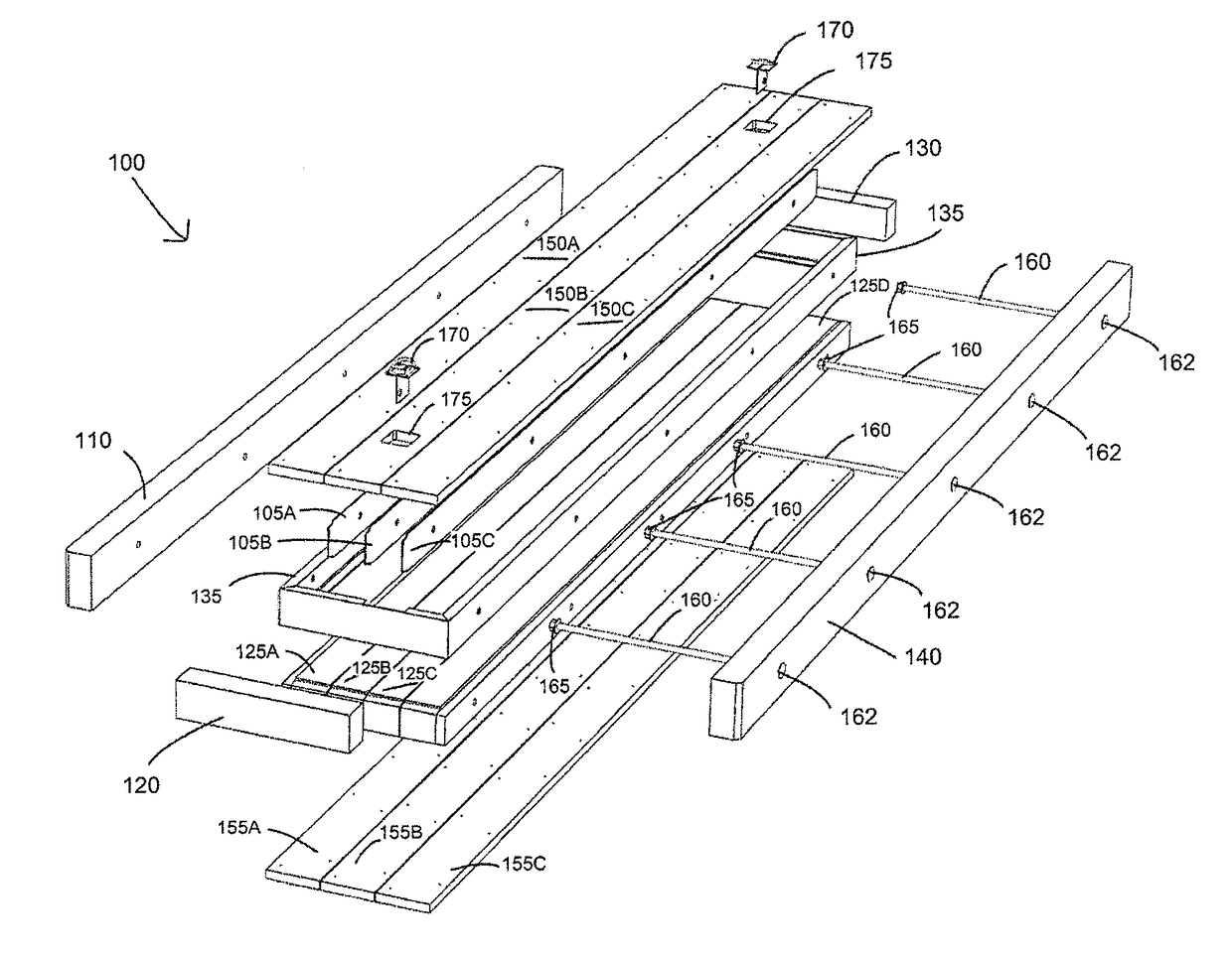
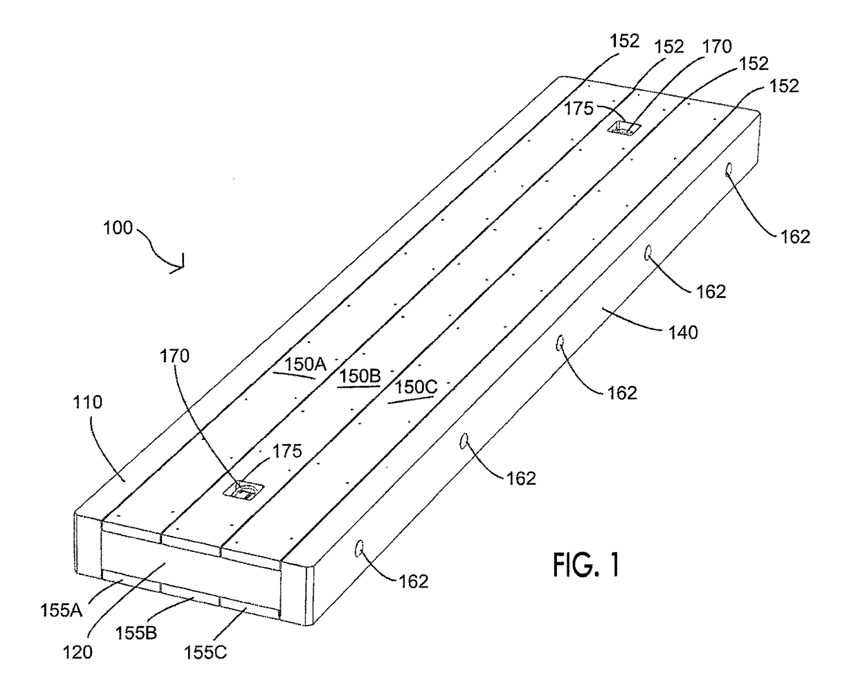
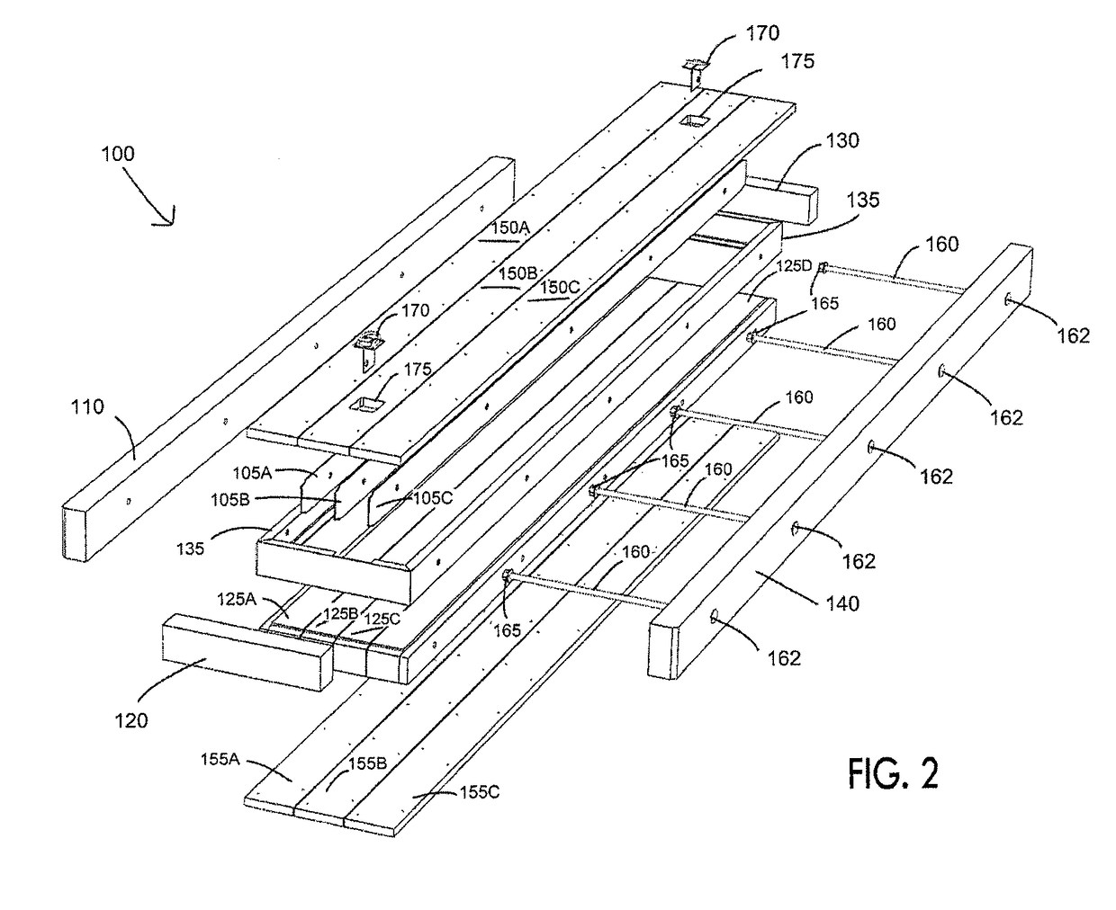
[0008]The present invention now satisfies these needs in the art by providing new crane mats with improved properties as well having newly designed and improved lifting elements and associated structures and arrangements for lifting and manipulation of these crane mats. These lifting elements, structures and arrangements also provide a lower profile where the lifting elements are maintained below the working surface of the mat to promote safety for workers. Also, the mat construction enables the use of lower cost core materials that are protected by a metal frame which in turn is protected by various outer boards, beams and / or bumper members.
[0019]Alternatively, the frame member may further comprise a metal frame that includes side and end members, and wherein the outer side members, side members of the frame and longitudinal members each include a plurality of spaced lateral apertures passing therethrough, with the lateral apertures being in alignment to form bores through the mat; wherein each joining member passes through each of the previously mentioned members through the aligned lateral apertures to hold the members together in the mat. The frame preferably includes one or a plurality of cross members attached to side members to strengthen the frame, with the longitudinal members located between cross members and with additional filler members located between the cross members and end members of the frame, wherein a joining member passes through the additional filler members through aligned lateral apertures therein to hold those members together in the mat. Thus, the one or more lifting elements are connected to a cross member to secure the lifting element to the mat.
[0020]In yet another embodiment, the recess provides a sufficient opening in the mat to expose a portion of the joining member and the lifting element comprise a ring, cable, or chain that receives the exposed joining member. Advantageously, the recess opening also provides sufficient space to receive and maintain the lifting element in the storage position beneath the working surface of the mat. If desired, the opening of the recess can be reinforced with metal plates or a collar which protects the opening from contact by the ring, chain or cable and which adds stability as the mat is being lifted or moved.
[0031]Generally, between 2 and 12 lifting elements are provided in the mat, preferably in a symmetrical pattern. The openings or recesses for at least two of the lifting elements are spaced about 1 to 3 feet from the front or rear ends of the mat so as to provide easy access by the crane or lifting device.
Problems solved by technology
There are concerns regarding the lifting and movement of such mats due to their relatively large sizes.
While the exposure of the joining or connecting rod facilitated lifting or moving operations, it presented an issue in that workers could inadvertently step into over the open hole that was provided around the connecting rod.
Method used
Image
Click on the blue label to locate the original text in one second.
Reading with bidirectional positioning of images and text.
Examples
Embodiment Construction
[0058]The new and improved crane mats of the present invention now provide a number of surprising advantages over conventional crane mats. The provision of a one or more lifting elements that are securely attached to these mats facilitates overhead lifting and manipulation of the mats in a much more secure manner. By securing the lifting element directly to the joining rod of the mat, the weight of the mat becomes directly distributed from the mat onto the joining rod to the lifting element. Prior crane mats included a large opening to expose the joining rod to enable a crane hook to access the rod for lifting. The provision of the lifting elements of the present invention now provides much smaller recesses and openings compared to conventional crane mats to avoid having workers operating on the upper surface of the mat from tripping over or stepping into the hole. In addition, the recesses and holes are sized and configured to receive the lifting element when not in use to provide ...
PUM
Property
Measurement
Unit
sizes
aaaaa
aaaaa
sizes
aaaaa
aaaaa
lengths
aaaaa
aaaaa
Abstract
An industrial mat having a supporting structure; an upper layer provided above the supporting structure for forming an upper surface of the mat, a lower layer provided below the supporting structure for providing a lower surface of the mat; and lifting elements attached to the upper layer, the lower layer or the supporting structure. The lifting elements include D-shaped members, O-shaped members, U-shaped members, eyelets, hooks, circular or polygonal rings, chains, or cables that are configured and dimensioned for attachment to attached to the supporting structure or the upper or lower layer with sufficient strength to provide certified overhead lifting of the mat for installation and reclamation thereof.
Description
CROSS-REFERENCE TO RELATED APPLICATIONS[0001]This application is a continuation-in-part of application Ser. No. 15 / 377,545 filed Dec. 13, 2016, which is a continuation-in-part of application Ser. No. 15 / 244,614 filed Aug. 23, 2016, which is a continuation-in-part of application Ser. No. 15 / 188,113 filed Jun. 21, 2016, which is a continuation-in-part of application Ser. No. 15 / 155,685 filed May 16, 2016, which is a continuation-in-part of application Ser. No. 15 / 081,340 filed Mar. 25, 2016, now U.S. Pat. No. 9,476,164, which is a continuation-in-part of application Ser. No. 15 / 056,212 filed Feb. 29, 2016, now U.S. Pat. No. 9,447,547, which is a continuation-in-part of application Ser. No. 14 / 839,888 filed Aug. 28, 2015, now U.S. Pat. No. 9,315,949, which claims the benefit of each of application Ser. Nos. 62 / 054,186 filed Sep. 23, 2014, 62 / 138,143 filed Mar. 25, 2015, and 62 / 158,196 filed May 7, 2015.[0002]Application Ser. No. 15 / 244,614 filed Aug. 23, 2016 claims the benefit of appl...
Claims
Application Information
Patent Timeline
Application Date:The date an application was filed.
Publication Date:The date a patent or application was officially published.
First Publication Date:The earliest publication date of a patent with the same application number.
Issue Date:Publication date of the patent grant document.
PCT Entry Date:The Entry date of PCT National Phase.
Estimated Expiry Date:The statutory expiry date of a patent right according to the Patent Law, and it is the longest term of protection that the patent right can achieve without the termination of the patent right due to other reasons(Term extension factor has been taken into account ).
Invalid Date:Actual expiry date is based on effective date or publication date of legal transaction data of invalid patent.