Connector

a technology of connecting rods and connectors, applied in the field of connecting rods, can solve the problems of disadvantageous contamination of liquid inside the flow path, slits are highly likely to be torn, and male connectors are difficult to prevent from entering the flow path, so as to prevent the slit of the valve from being torn, prevent the male connector from entering, and maintain the air tightness of the valve

Active Publication Date: 2018-02-27
TERUMO KK
View PDF22 Cites 1 Cited by
  • Summary
  • Abstract
  • Description
  • Claims
  • Application Information

AI Technical Summary

Benefits of technology

[0009]In view of the above problems, it is one object of embodiments of the present invention to provide a connector that is capable of reliably allowing flow paths of a male connector and a housing to communicate with each other without causing the tip end of the male connector to penetrate a valve, and suppressing or preventing a slit of the valve from being torn.
[0012]Further, since the stopping portion of the housing defines the insertion length of the male connector, it is possible to prevent the male connector from penetrating the valve. Therefore, it is possible to reliably prevent the male connector from entering the flow path. Further, since the valve is not caused to deform more than necessary, it is possible to suppress or prevent the slit of the valve from being torn, and thereby maintain the air-tightness of the valve.
[0013]With the connector having the above configuration, since the stopping portion defines the insertion length of the male connector, the valve can be sufficiently opened without causing the tip end of the male connector to penetrate the valve. Therefore, it is possible to reliably prevent the male connector from entering the flow path, and prevent the slit of the valve from being torn.

Problems solved by technology

However, in the connector disclosed in JP '983, when a user pushes a male connector into the fitting hole, a slit of the valve may be torn.
As a result, the slit is highly likely to be torn.
Thus, if the tip end of the male connector has bacteria adhering thereon, the liquid inside the flow path will be disadvantageously contaminated.

Method used


Image

  • Connector
  • Connector
  • Connector

Examples


first embodiment

1. First Embodiment of Connector

[Configuration Example of Connector]

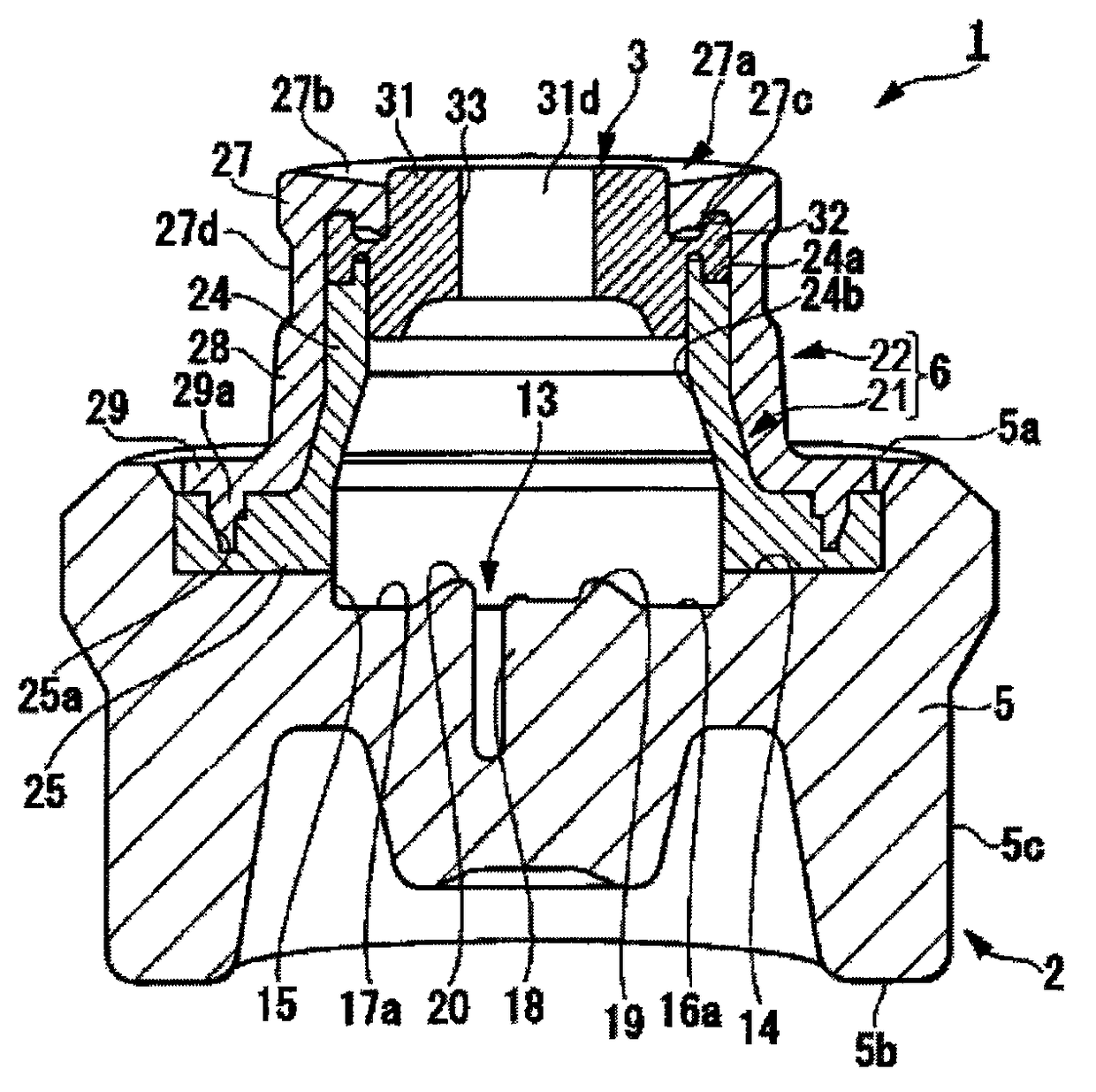
[0024]First, the configuration of a connector according to a first embodiment of the present invention will be described with reference to FIGS. 1 to 4.

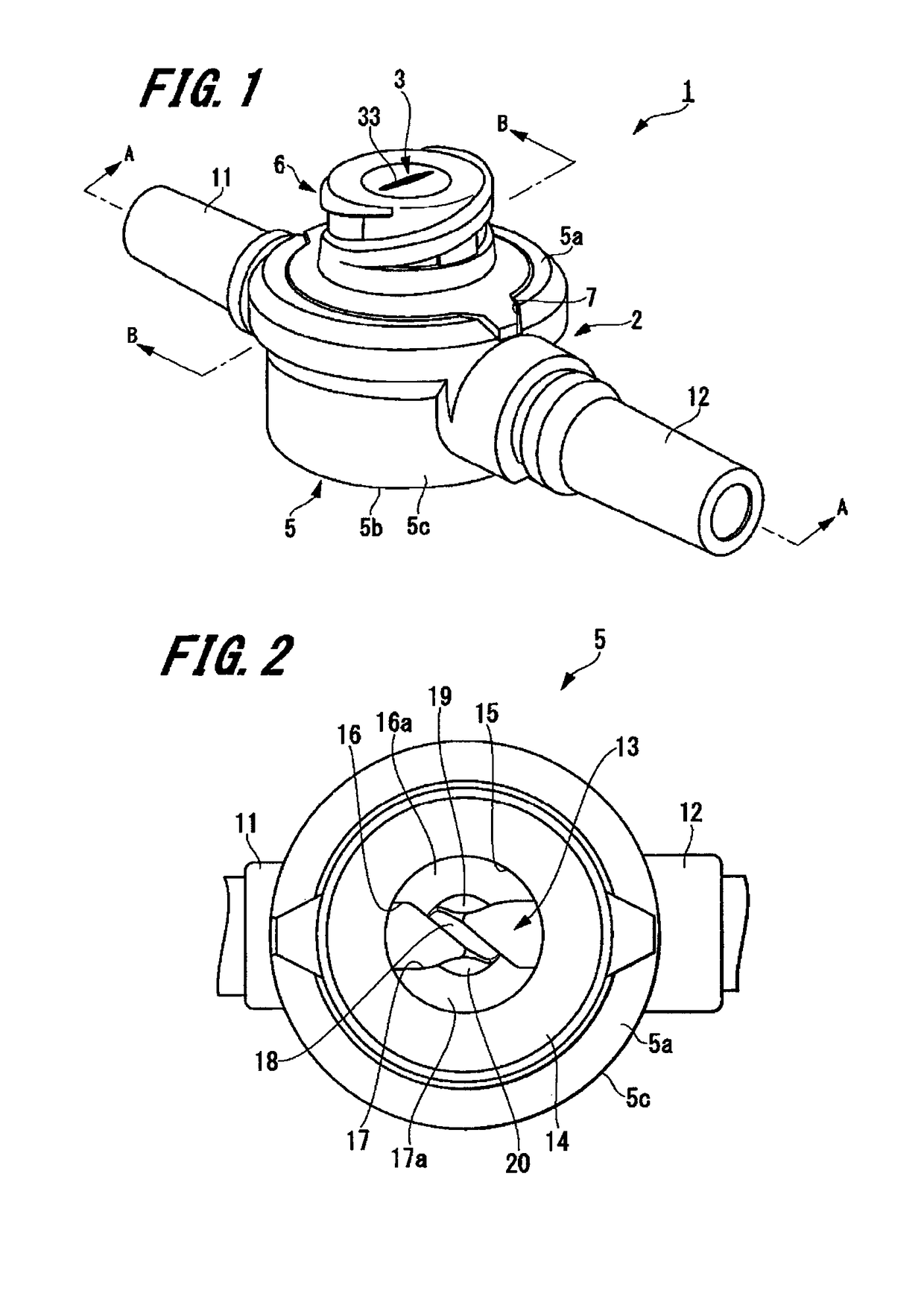
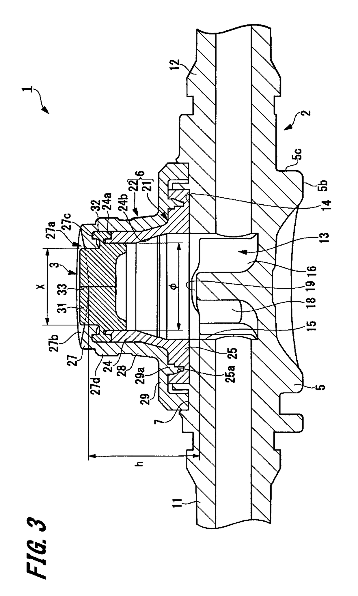
[0025]FIG. 1 is a cross-sectional view illustrating the connector according to the first embodiment. FIG. 2 is a plan view of a housing main body of the connector according to the first embodiment. FIG. 3 is a cross-sectional view taken along line A-A of FIG. 1. FIG. 4 is a cross-sectional view taken along line B-B of FIG. 1.

[0026]As illustrated in FIG. 1, a connector 1 includes a housing 2, and a valve 3 fixed to the housing 2.

[Housing]

[0027]Examples of the material of the housing 2 include polyolefins such as polyethylene, polypropylene, ethylene-propylene copolymers, and ethylene-vinyl acetate copolymers (EVA) and the like, polyvinyl chloride, polyvinylidene chloride, polystyrene, polyamide, polyimide, polyamide-imide, polycarbonate, poly(4-methylpentene-1), ionom...

second embodiment

2. Second Embodiment of Connector

[0101]Next, a connector according to the second embodiment of the present invention will be described with reference to FIG. 9.

[0102]FIG. 9 is a cross-sectional view illustrating a state in which a male connector 100 is connected to the connector according to the second embodiment of the present invention.

[0103]The connector of the second embodiment has the same configuration as that of the connector 1 of the first embodiment. The connector of the second embodiment differs from the connector 1 of the first embodiment only in a state of a valve 63 when the male connector 100 is connected thereto. Thus, herein the description will focus on the valve 63, and the same components as those of the connector 1 will be denoted by the same reference numerals and description thereof will be omitted.

[0104]As illustrated in FIG. 9, the valve 63 of a connector 61 has the same configuration as that of the valve 3 of the first embodiment. The valve 63 differs from t...


PUM


Abstract

A connector includes a housing having a flow path through which liquid passes, and a male connector connecting portion having a substantially circular tube hole communicating with the flow path; and a valve formed of an elastic material and adapted to block the male connector connecting portion of the housing. The valve includes a top surface exposed from the male connector connecting portion, a bottom surface opposite to the top surface, and a slit opened at least on the top surface or the bottom surface. The housing includes a stopping portion configured to be engaged with a tip end of a male connector to define an insertion length of the male connector.

Description

CROSS-REFERENCE TO RELATED APPLICATIONS[0001]This application is a continuation application filed under 35 U.S.C. 111(a) claiming the benefit under 35 U.S.C. §§ 120 and 365(c) of PCT International Application No. PCT / JP2013 / 052133 filed on Jan. 31, 2013, which is based upon and claims the benefit of priority of Japanese Application No. 2012-018326 filed on Jan. 31, 2012, the entire contents of which are hereby incorporated by reference in their entireties.BACKGROUND[0002]The present disclosure relates to a connector capable of connecting a male connector of various medical instruments, infusion containers or the like in a liquid-tight manner.[0003]Conventionally, when performing fluid infusion, blood transfusion, hemodialysis or the like, liquid is infused into the body using a medical tube. Further, in the case where another liquid such as a medical solution or the like is to be merged into the liquid within the tube, a connector capable of connecting a male connector of a syringe,...

Claims


Application Information

Patent Timeline
Patent Type & Authority Patents(United States)
IPC IPC(8): A61M39/10A61M39/26A61M39/04
CPCA61M39/10A61M39/26A61M39/045A61M39/105Y10T137/9029A61M2039/1083A61M2039/1088A61M2205/0216Y10T137/0491A61M2039/1072
Inventor UEDA, YASUHIROZUSHI, YASUNOBUTAOKA, KOUHEI
Owner TERUMO KK
Why Eureka
Try Eureka