Drill guide used in woodworking for preparing pocket joints

a drill guide and pocket joint technology, applied in the field of drill guide used for preparing pocket joints, can solve the problems of affecting the quality of the drill bit, unable to provide any means for drawing off wood chips, and affecting the quality of the pocket joints

Inactive Publication Date: 2007-08-30
CHIANG VANCE
View PDF18 Cites 24 Cited by
  • Summary
  • Abstract
  • Description
  • Claims
  • Application Information

AI Technical Summary

Problems solved by technology

However, the disclosure of U.S. Pat. No. 4,955,766 does not provide any means for drawing off wood chips during drilling.
Deposited wood chips will affect the quality of the pocket joints, and may cause the drill bit to be damaged.
Furthermore, the disclosure of U.S. Pat. No. 4,955,766 can only drill a pocket of fixed specification.

Method used


Image

  • Drill guide used in woodworking for preparing pocket joints
  • Drill guide used in woodworking for preparing pocket joints
  • Drill guide used in woodworking for preparing pocket joints

Examples


Embodiment Construction

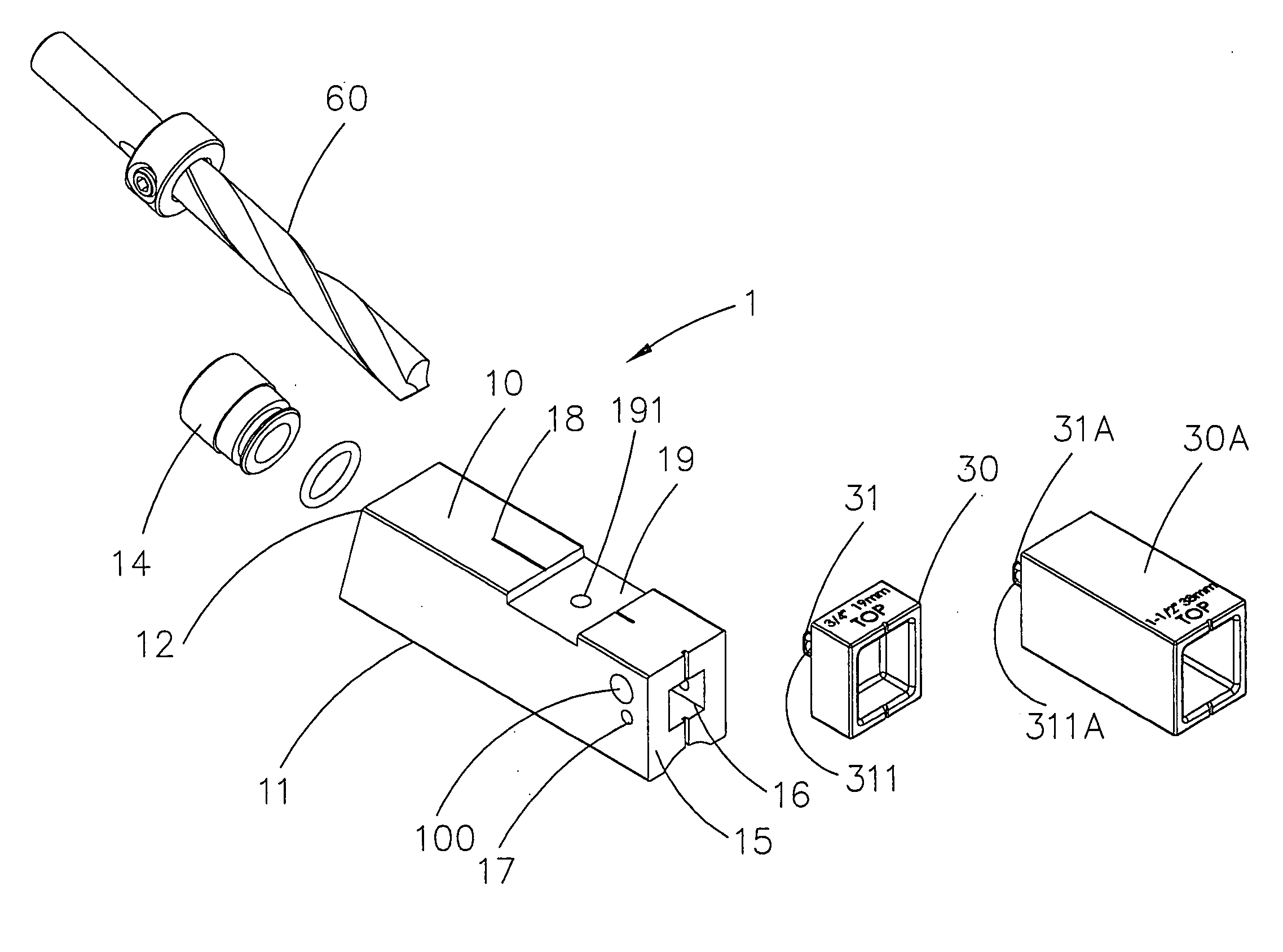
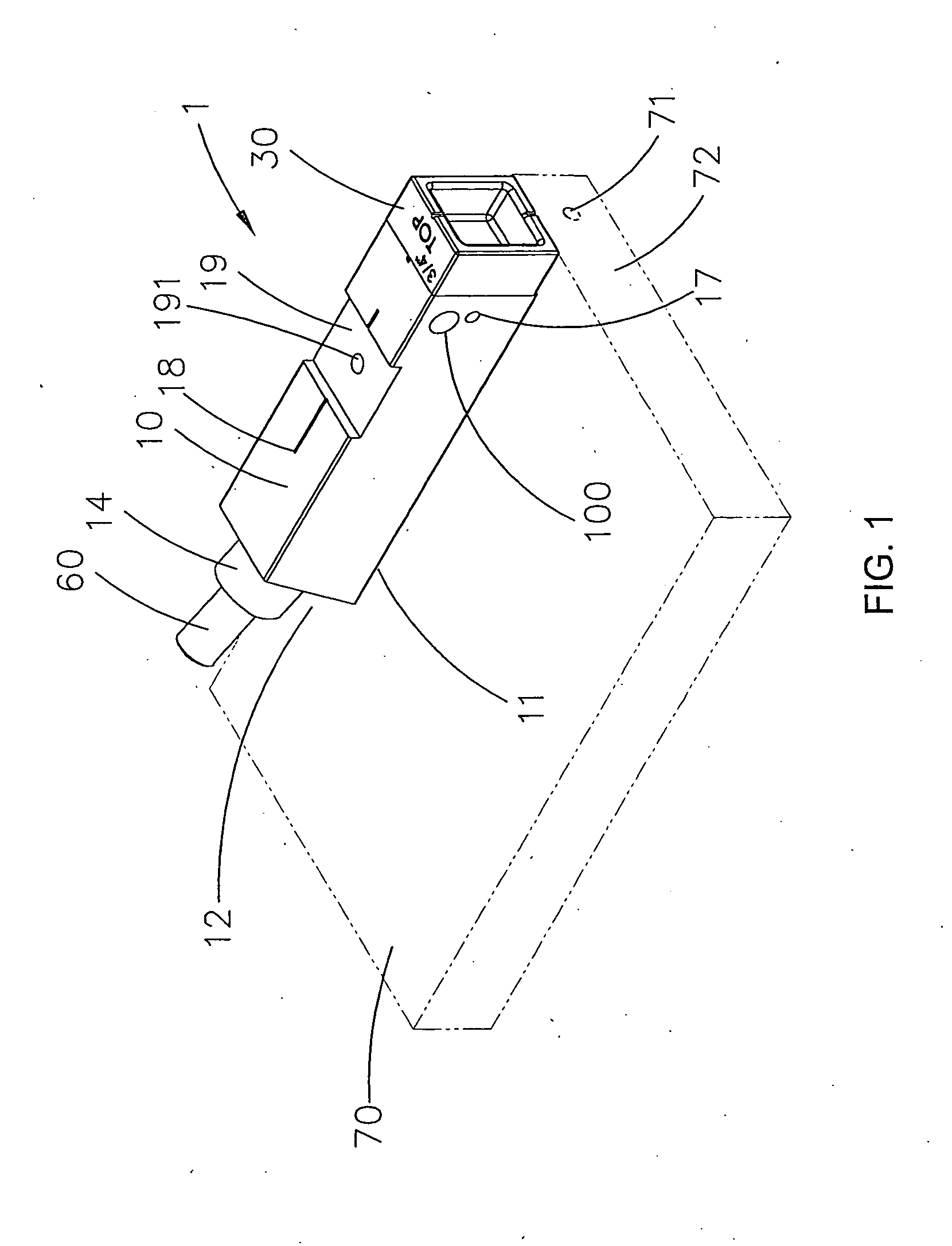
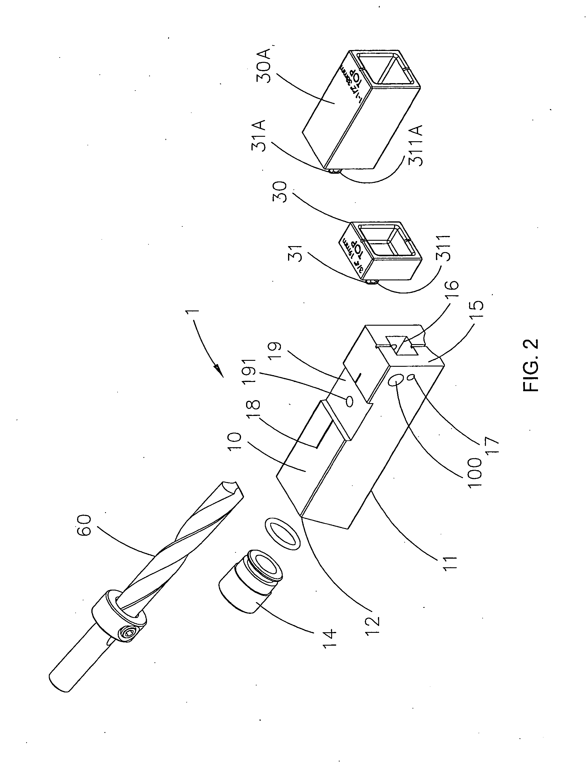
[0021] Referring to the drawings and initially to FIGS. 1-5, a drill guide used in woodworking for preparing pocket joints in. accordance with the present invention comprises a first guide member (1) with a cuboid body (10). The cuboid body (10) has a first datum plane (11) form on a bottom thereof for abutting a top surface of a workpiece (70) during operating. With reference to FIGS. 3 and 4, the cuboid body (10) has an inclined plane (12) formed on a front end thereof and a cavity (13) defined in the front end thereof. The cavity (13) has two opposite ends respectively and slantingly extends to the inclined plane (12) and the first datum plane (11) of the cuboid body (10). A guide sleeve (14) is longitudinally and detachably mounted in the front end of the cuboid body (10) and abuts the inclined plane (12). The guide sleeve (14) extends into the cavity (13) for guiding a drill bit (60) into the cavity (13) and drilling an inclined hole (71) in the workpiece. The guide sleeve (14)...


PUM

PropertyMeasurementUnit
thicknessaaaaaaaaaa
distanceaaaaaaaaaa
diameteraaaaaaaaaa

Abstract

A drill guide used in woodworking for preparing pocket joints includes a guide member with a cuboid body. The cuboid body has an inclined plane formed on a front end thereof and a cavity defined in the front end thereof. The cavity has two opposite ends respectively and slantingly extending to the inclined plane and the first datum plane. A guide sleeve is longitudinally and detachably mounted in the front end of the cuboid body and abuts the inclined plane. The guide sleeve extends into the cavity for guiding a drill bit into the cavity and drilling an inclined hole in the workpiece. The cuboid body has a second datum plane formed on a rear end thereof. An axis of the drill bit passes through a central plane of the workpiece on a rear distal edge when the second datum plane aligns with the rear distal edge.

Description

BACKGROUND OF THE INVENTION [0001] 1. Field of the Invention [0002] The present invention relates to a woodworking apparatus, and more particularly to a drill guide used for preparing pocket joints. [0003] 2. Description of Related Art [0004] U.S. Pat. No. 4,955,766 discloses a holding fixture for drilling pocket joints, in which a drilling bit 1 is used having a pocket forming portion and a smaller diameter pilot hole forming portion for drilling pocket joints (pilot hole 3 and pocket 4) on workpieces 2 and 2A for mounting screws 5, and an over-center toggle clamp is used for holding the workpiece. According to U.S. Pat. No. 4,955,766, a guide line must be marked on the workpiece before drilling pocket joints, and when a pilot hole is formed, the workpiece must be fixed in position by the over-center toggle clamp so that the desired pocket can be processed. However, the disclosure of U.S. Pat. No. 4,955,766 does not provide any means for drawing off wood chips during drilling. Depo...

Claims


Application Information

Patent Timeline
Patent Type & Authority Applications(United States)
IPC IPC(8): B23B47/28
CPCB23B47/287B23B2260/004Y10T408/567B23B2260/134B23B2270/16B23B2260/088
Inventor CHIANG, VANCE
Owner CHIANG VANCE
Why Eureka
Try Eureka