Electromagnetic musical instrument frequency conversion systems and related methods

a technology of frequency conversion system and musical instrument, applied in the field of musical instruments, can solve problems such as more complex electromagnetic field solutions, and achieve the effect of improving the frequency conversion rate and frequency conversion ra

Inactive Publication Date: 2007-09-20
STONEBACK RUSSELL
View PDF71 Cites 19 Cited by
  • Summary
  • Abstract
  • Description
  • Claims
  • Application Information

AI Technical Summary

Benefits of technology

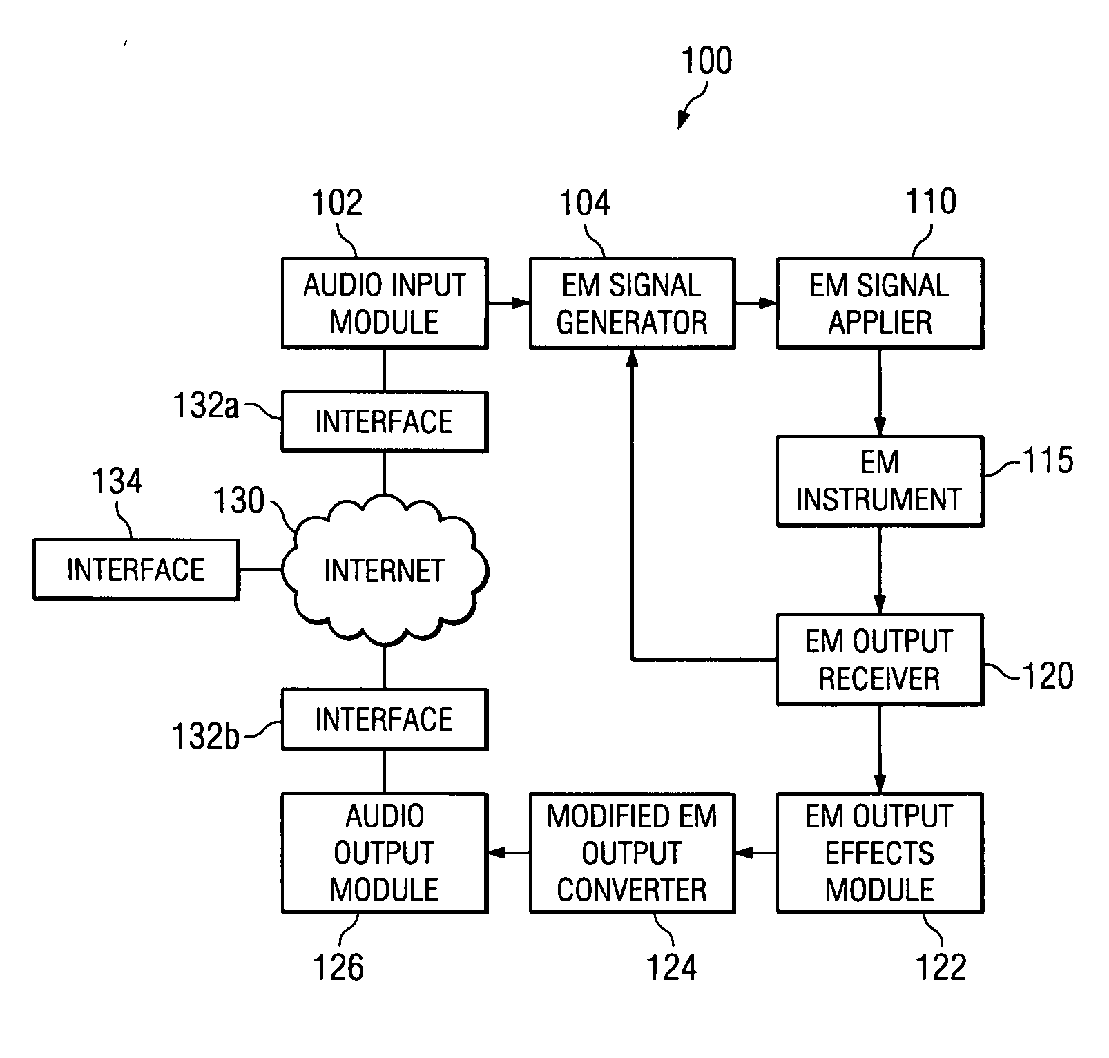
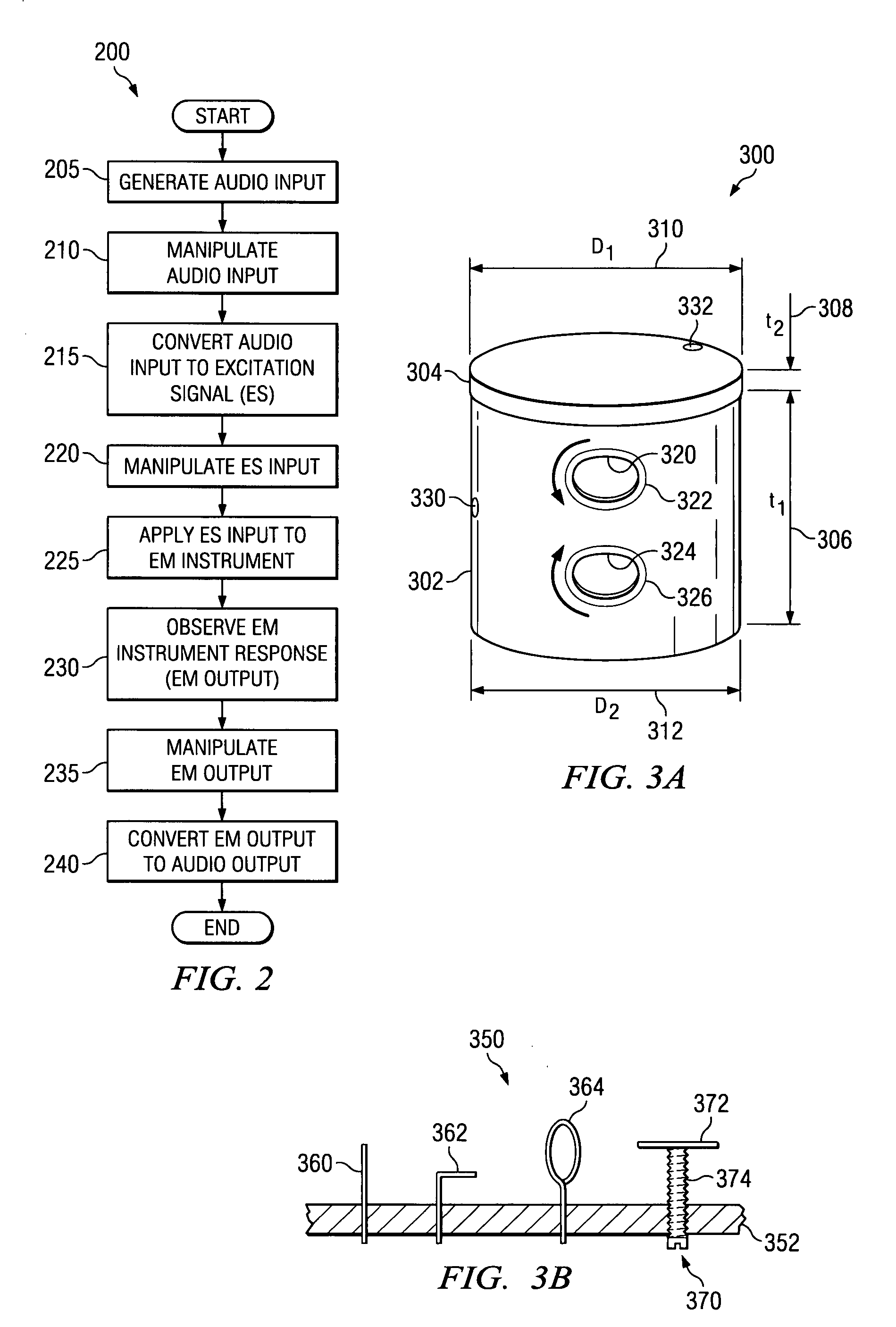
[0024] The problems presented in traditional musical instruments are solved by the systems and methods of the present invention. In accordance with one embodiment of the present invention, an electromagnetic (EM) musical instrument is provided. The EM musical instrument comprises a body comprising a shape and having EM characteristics that differ from one or more EM characteristics of a free space adjacent to the EM musical instrument. A port is coupled to the body and configured to receive an excitation signal and to apply the received excitation signal to the body. Accordingly, an EM musical instrument allows novel musical sounds to be created.
[0030] In an alternate embodiment, the method further comprises manipulating the electromagnetic musical signal for audio effects. In an alternate embodiment, the method further comprises frequency converting the electromagnetic musical signal to an audible signal. In an alternate embodiment, the method further comprises receiving user input and wherein the excitation signal is generated in response to received user input. In still another embodiment, the method further comprises polarizing the excitation signal to generate a polarized signal and applying the polarized signal to the EM musical instrument. Accordingly, further novel musical sounds can be created.

Problems solved by technology

However, the more complex Electromagnetic field solution nevertheless encompasses the Acoustic solution.

Method used


Image

  • Electromagnetic musical instrument frequency conversion systems and related methods
  • Electromagnetic musical instrument frequency conversion systems and related methods
  • Electromagnetic musical instrument frequency conversion systems and related methods

Examples


Embodiment Construction

[0041] All references cited herein are incorporated by reference to the maximum extent allowable by law. To the extent a reference may not be fully incorporated herein, it is incorporated by reference for background purposes and indicative of the knowledge of one of ordinary skill in the art.

[0042] In the following detailed description of the preferred embodiments, reference is made to the accompanying drawings, which form a part hereof, and in which is shown by way of illustration specific preferred embodiments in which the invention may be practiced. These embodiments are described in sufficient detail to enable those skilled in the art to practice the invention, and it is understood that other embodiments may be utilized and that logical mechanical and electrical changes may be made without departing from the spirit or scope of the invention. To avoid detail not necessary to enable those skilled in the art to practice the invention, the description may omit certain information k...


PUM


Abstract

A method for generating electromagnetic (EM) music through excitation of an EM Musical Instrument is provided. An input queue, comprised of three sub-queues, receives three input audio queues. An EM excitation signal is generated based on the received input audio queues. The EM excitation signal is applied to the EM Musical Instrument. A measured response is generated, based on a response of the EM Musical Instrument to the EM excitation signal. Various time marks are marked in the measured response. Selected portions of the measured response are discarded based on particular time marks, generating a newly measured sample set. The newly measured samples are joined to a previously measured sample set of an output queue based on alignment of time marks. Various alternate embodiments and supporting systems are also provided.

Description

[0001] This application claims priority and the benefit under 35 U.S.C. §119(e) from U.S. provisional patent application 60 / 702,184 for “Electromagnetic Musical Instruments and Related Method” filed Jul. 25, 2005. This application is a continuation of copending U.S. patent application Ser. No. 11 / 325,296 for “Electromagnetic Musical Instrument Systems and Related Method,” filed Jan. 4, 2006, which is hereby incorporated by reference, and claims priority and the benefit under 35 U.S.C. §120.BACKGROUND [0002] 1. Field of the Invention [0003] The present invention relates generally to musical instruments and in particular to electromagnetic musical instrument systems and methods. [0004] 2. Description of Related Art [0005] Generally, Acoustic musical instruments produce sounds that are audible to the human ear and travel from the instrument or other sound source through propagation of pressure and velocity waves, typically through the atmosphere. These waves are comprised of material p...

Claims


Application Information

Patent Timeline
Patent Type & Authority Applications(United States)
IPC IPC(8): G10H1/00
CPCG10H1/0091G10H2250/315G10H5/14G10H2210/231G10H2210/235G10H2210/251G10H2210/281G10H2210/311G10H2220/195G10H2220/411G10H2230/045G10H2230/135G10H2240/305G10H2240/311G10H3/26
Inventor STONEBACK, RUSSELL
Owner STONEBACK RUSSELL
Why Eureka
Try Eureka