Forward Acting Turnover Apparatus and Method

Inactive Publication Date: 2007-09-20
KAUPPILA RICHARD +1
View PDF4 Cites 7 Cited by
  • Summary
  • Abstract
  • Description
  • Claims
  • Application Information

AI Technical Summary

Benefits of technology

[0007] Sets of flipper arms are pivotally mounted to the conveyor drive elements at spaced intervals corresponding to the lug spacing, which arms are successively operated by engagement with stationary cams at a turnover station along the conveyor. The flipper arms when operated engage the trailing side of each piece which are located to extend forwardly from the lug and raise the piece to an on edge position. Since the drag structure causes the now on edge piece to be urged back against the forwardly projecting arms in the set, the top of the on edge piece is tipped forwardly to cause the piece to fall in a forward direction, thereby completing the turnover process.

Problems solved by technology

Since these mechanisms usually are synchronized with the conveyor, this becomes more difficult at these higher speeds.

Method used


Image

  • Forward Acting Turnover Apparatus and Method
  • Forward Acting Turnover Apparatus and Method
  • Forward Acting Turnover Apparatus and Method

Examples


Embodiment Construction

[0018] In the following detailed description, certain specific terminology will be employed for the sake of clarity and a particular embodiment described in accordance with the requirements of 35 USC 112, but it is to be understood that the same is not intended to be limiting and should not be so construed inasmuch as the invention is capable of taking many forms and variations within the scope of the appended claims.

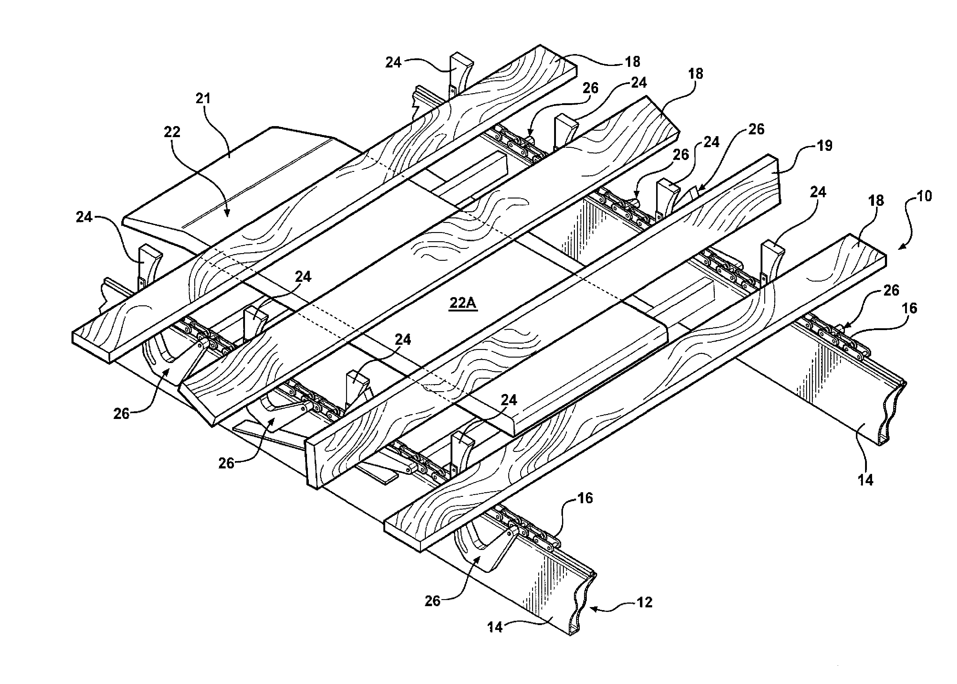
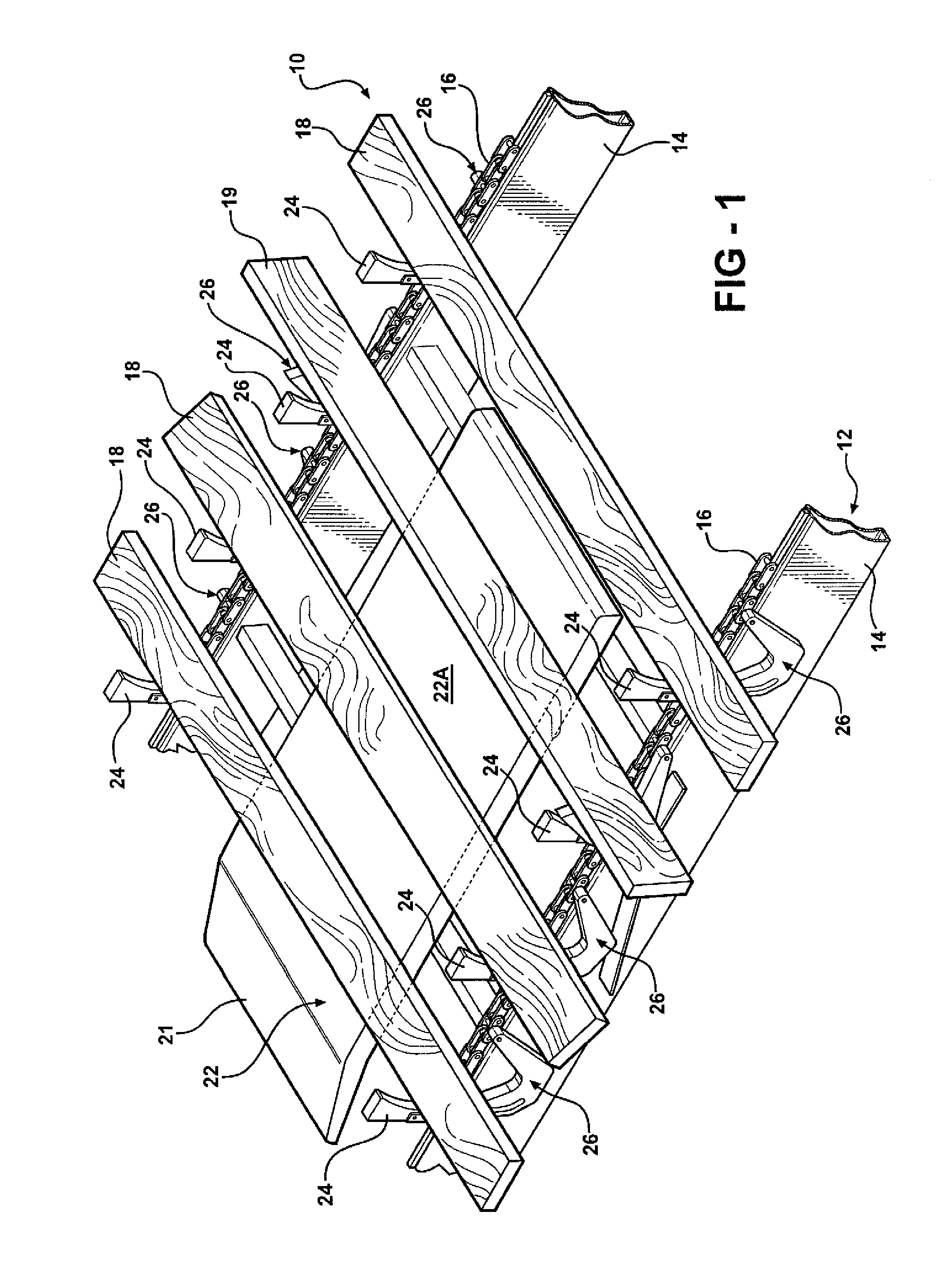
[0019] Referring to the drawings, and particularly FIGS. 1 and 2, an apparatus 10 according to the present invention includes a conveyor 12 a section of which is shown in FIG. 1 here comprised of a series of parallel support rails 14 and conveyor drive elements supported and guided thereon, here comprised of recirculating chain loops 16 designed to frictionally engage the underside of a series of articles or pieces 18 to be conveyed sideways. While boards 18 are shown the pieces 18 could be a variety of items, such as panels, doors, etc. The board pieces 18 are loaded ...


PUM


Abstract

A turnover apparatus and method for turning over articles such as lumber or board pieces being conveyed sideways on one or more conveyor drive loops in which each piece is retarded on the conveyor loops by structure engaging the underside of the pieces to shift the piece back against a lug mounted on each respective conveyor chain loop, the piece thereafter rotated up to an on edge position by flipper arms also mounted on the conveyor loops which each engage a cam ramp at a turnover station, the piece thereafter tipped over forwardly to complete the turnover. Optional pivoted let down arms may be arranged to engage the leading side of the pieces to controllably lower the same by motion induced by second cams at the turnover station.

Description

CROSS REFERENCE TO RELATED APPLICATION [0001] This application is a continuation-in-part of U.S. Ser. No. 10 / 728,183 filed on Dec. 4, 2003, now U.S. Pat. No. 7,153,086BACKGROUND OF THE INVENTION [0002] In various processing applications, it is sometimes necessary to turn over work pieces being moved along a conveyor system, such as to inspect both sides of lumber pieces in a saw mill being transported past an inspection station. Such processes are often conducted at high rates so that the turnover or flipping mechanism must also be reliably capable of operating at a high rate of speed. Since these mechanisms usually are synchronized with the conveyor, this becomes more difficult at these higher speeds. [0003] In U.S. Pat. No. 7,153,086 referenced above, there is described an apparatus and method which avoids the need for such synchronization by mounting a series of flipper arms to the conveyor drive elements, i.e. the chain or belt loops, etc. That patent is hereby incorporated by r...

Claims


Application Information

Patent Timeline
IPC IPC(8): B65G47/248
CPCB65G2201/0282B65G47/248
Inventor KAUPPILA, RICHARDHINTSALA, DANIEL
Owner KAUPPILA RICHARD
Why Eureka
Try Eureka