
Combination sealing system for sliding door/window

a sealing system and sliding door technology, applied in the field of sealing systems, can solve the problems of insufficient seals, inability to prevent elements such as noise, weather, water, insects, and noise from breaching the seals, and achieve the effect of creating seals

Inactive Publication Date: 2007-10-11
SECURA SEAL TECH
View PDF99 Cites 45 Cited by
  • Summary
  • Abstract
  • Description
  • Claims
  • Application Information

AI Technical Summary

Problems solved by technology

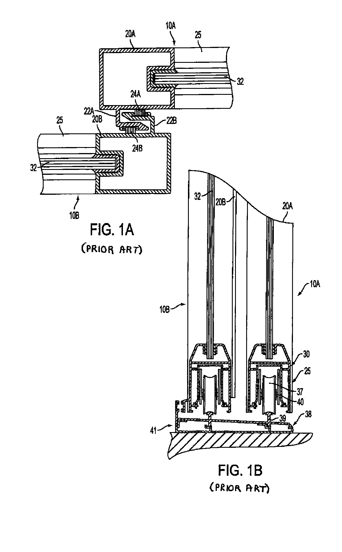
An issue associated with these types of panels is the integrity of the seals between the panels and the frame and between adjacent meeting stiles of a pair of panels.
In many instances, these seals are an insufficient barrier in preventing the transfer of such environmental elements as noise, weather, water, and insects from one side of the panel to the other side of the panel.
These seals 24A, 24B, however, are not always capable of preventing elements, such as noise, weather, water, and insects, from breaching the seals.
In many instances, however, this weather stripping fails to act as a sufficient seal between the panels and frame.
Another issue prevalent associated with the seals between a frame and panel or between adjacent panels is that these seals can become disjoined.
Either intentionally or unintentionally, the alignment between the frame and panel or between adjacent panels may be disturbed which can degrade the quality of the seal, since, in many instances, the integrity of the seal relies upon these members having certain positional relationships relative to one another.
Yet another issue associated with the movement of one or more panels relative to the frame is structural integrity and / or security of the panels relative to the frame.
Means for providing these separate functionalities, however, can be incompatible with one another, and the means employed to provide both functions often involve tradeoffs that reduce the effectiveness of both functions.

Method used


Image

  • Combination sealing system for sliding door/window
  • Combination sealing system for sliding door/window
  • Combination sealing system for sliding door/window

Examples


Embodiment Construction

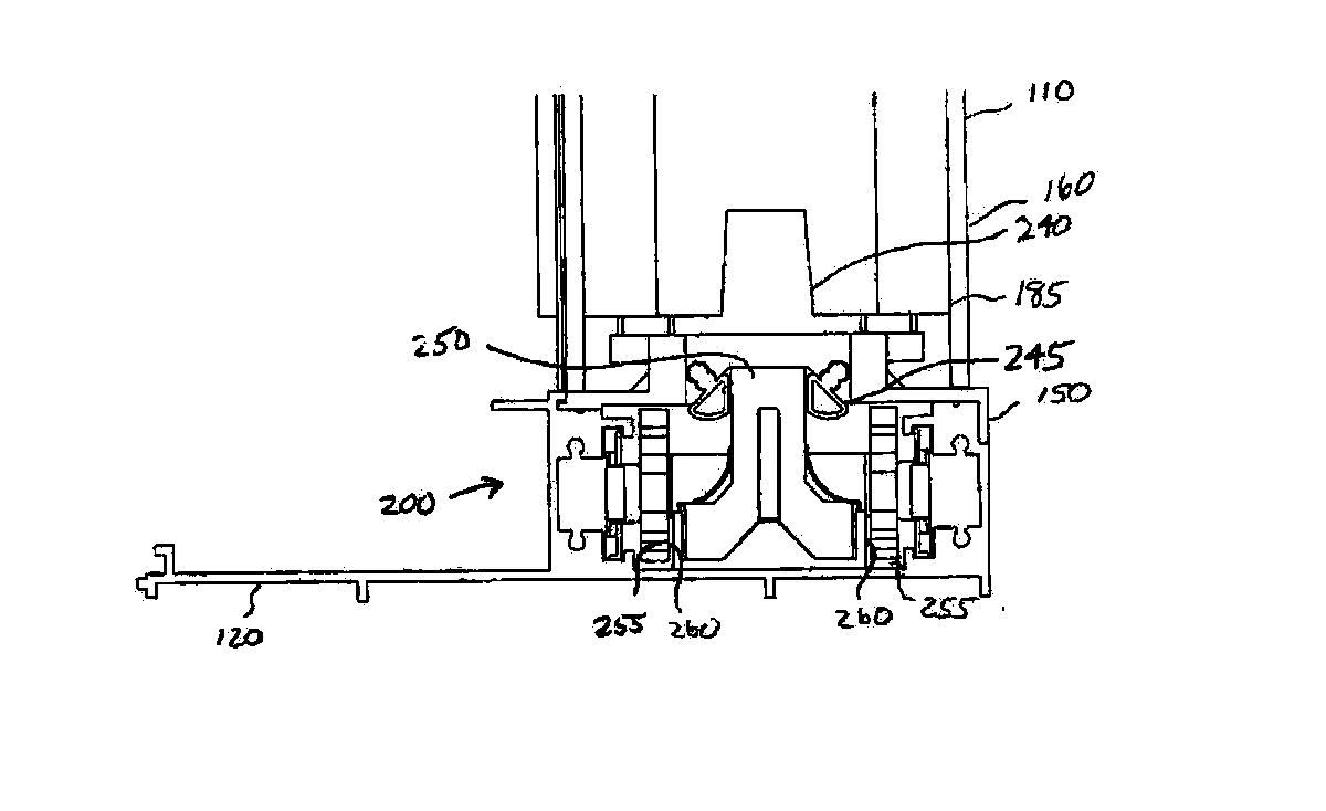
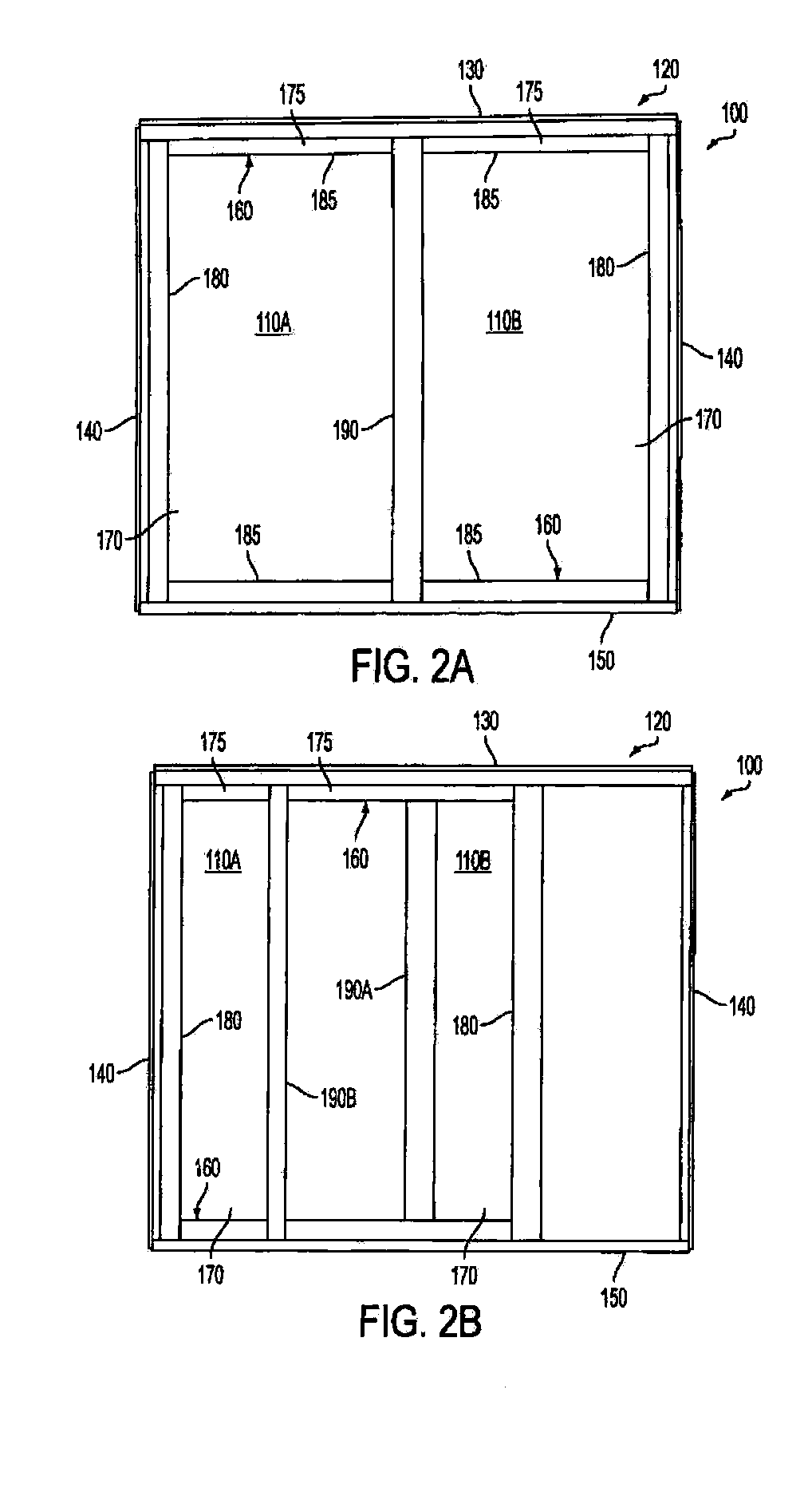
[0030]FIGS. 2A and 2B illustrate an exemplar door / window system 100 for use with the improved sealing system 200. The sealing system 200 can be used with many types of doors and / or windows, and the sealing system 200 is not limited to the particular door / window system 100 illustrated. For example, the sealing system 200 may be used with pocket doors, sliding doors, French doors, entry doors, garage doors, sliding windows, single-hung windows, double-hung windows, casement windows, and awning windows. The door / window system 100 includes panels 110A, 110B connected to a stationary frame 120.

[0031] The door / window system 100 is not limited in the manner in which the panel 110 moves relative to the frame 120. For example, the panels 110A, 110B may pivot relative to the frame 120. In certain aspects of the door / window system 100, however, either one or both of the panels 110A, 110B may move relative to the frame 120 along a plane parallel to a longitudinal axis of one of the surfaces (e...


PUM

PropertyMeasurementUnit
flexibleaaaaaaaaaa
thresholdaaaaaaaaaa
translucentaaaaaaaaaa

Abstract

A combined sealing system for connecting a panel to a frame includes a first sealing system and a second sealing system. The first sealing system connects a first surface of the panel to a first surface of the frame, and the first sealing system has a first movable member movable along a first direction. The second sealing system connects a second surface of the panel to a second surface of the frame, and the second sealing system has a second movable member movable along a second direction. The combined sealing system has an unlocked configuration and a locked configuration. In the unlocked configuration, the panel is movable relative to the frame along a third direction. The first and second directions not parallel to the third direction.

Description

CROSS-REFERENCE TO RELATED APPLICATIONS [0001] This application is a Continuation-In-Part of U.S. application Ser. No. 11 / 322,952, filed on Dec. 30, 2005, incorporated herein by reference in its entirety.BACKGROUND OF THE INVENTION [0002] 1. Field of the Invention [0003] The disclosure relates generally to sealing systems for use with panels, such as a door or a window, within a frame and, more specifically, to a sealing system for providing an improved seal between meeting stiles of adjacent panels and between a panel and frame. [0004] 2. Description of the Related Art [0005] Certain types of panels, such as doors and windows, are positioned within openings of a wall and / or other structures using a frame. These panels may also open and close by sliding back and forth within the frame. An issue associated with these types of panels is the integrity of the seals between the panels and the frame and between adjacent meeting stiles of a pair of panels. In many instances, these seals ar...

Claims


Application Information

Patent Timeline
Patent Type & Authority Applications(United States)
IPC IPC(8): E06B1/04
CPCE06B7/23E06B3/4609
Inventor SPEYER, WILLIAM KIPTHIELMANN, JONATHAN D.MAMMOLITO, DANIEL P.
Owner SECURA SEAL TECH
Learn More